Infiniti Q45. Manual - part 876
ELECTRICALLY CONTROLLED POWER STEERING SYSTEM
STC-7
[WITHOUT REAR ACTIVE STEER]
C
D
E
F
H
I
J
K
L
M
A
B
STC
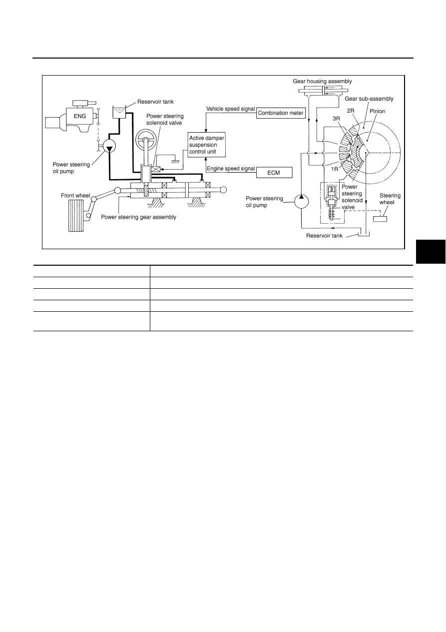
System Diagram
NGS0005W
COMPONENTS FUNCTION DESCRIPTION
SGIA1395E
Component parts
Function
Active damper suspension control unit
Controls power steering solenoid valve (with fail-safe function).
Power steering solenoid valve
Controls oil pressure in gear housing assembly.
Combination meter
Combination meter sends vehicle speed signal to active damper suspension control unit.
ECM
ECM sends engine speed signal to active damper suspension control unit. (For fail-safe
conditions)