Infiniti Q45. Manual - part 833
AUTOMATIC DRIVE POSITIONER
SE-87
C
D
E
F
G
H
J
K
L
M
A
B
SE
3.
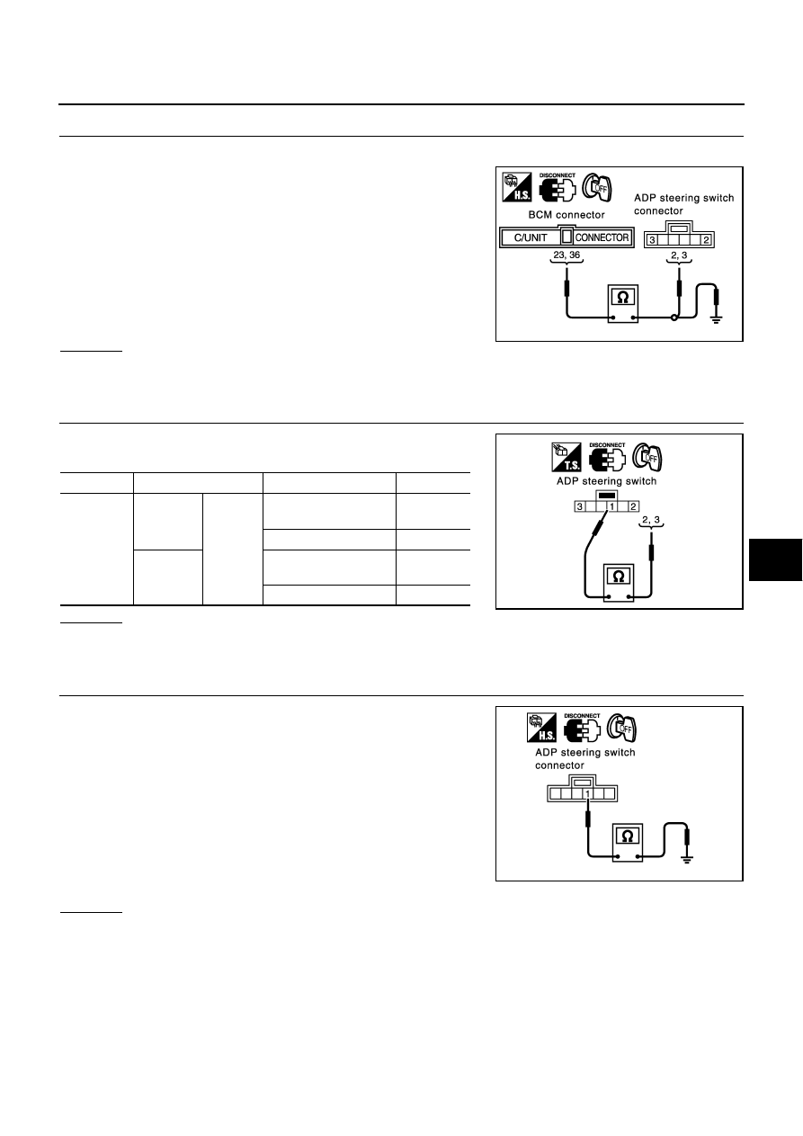
CHECK HARNESS CONTINUITY
1.
Disconnect BCM connector and ADP steering switch connector.
2.
Check continuity between BCM connector M4 terminals 23, 36
and ADP steering switch connector M51 terminals 2, 3.
3.
Check continuity between BCM connector M4 terminals 23, 36
and ground.
OK or NG
OK
>> GO TO 4.
NG
>> Repair or replace harness between BCM and ADP steering switch.
4.
CHECK ADP TILT STEERING SWITCH
Check continuity between ADP steering switch connector M51 termi-
nal 2, 3 and 1.
OK or NG
OK
>> GO TO 5.
NG
>> Replace ADP steering switch.
5.
CHECK ADP STEERING SWITCH GROUND CIRCUIT
Check continuity between ADP steering switch connector M51 termi-
nal 1 and ground.
OK or NG
OK
>> Check the harness and connector.
NG
>> Repair or replace harness between ADP steering switch and ground.
23 (W/R) – 3 (W/R)
: Continuity should exist.
36 (Y/G) – 2 (Y/G)
: Continuity should exist.
23 (W/R) – Ground
: Continuity should not exist.
36 (Y/G) – GRound
: Continuity should not exist.
PIIA3309E
Connector
Terminals
Condition
Continuity
M51
2
1
Tilt switch ON
(UP operation)
Yes
Tilt switch OFF
No
3
Tilt switch ON
(DOWN operation)
Yes
Tilt switch OFF
No
PIIA4482E
1 (B) – Ground
: Continuity should exist.
PIIA3310E