Infiniti Q45. Manual - part 831
AUTOMATIC DRIVE POSITIONER
SE-79
C
D
E
F
G
H
J
K
L
M
A
B
SE
3.
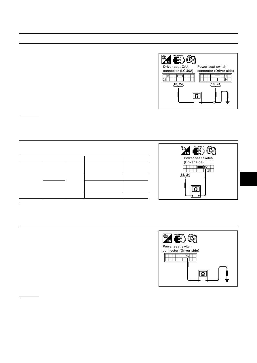
CHECK HARNESS CONTINUITY
1.
Disconnect driver seat control unit connector and power seat switch (driver side) connector.
2.
Check continuity between driver seat control unit connector
B143 terminals 18, 24 and power seat switch (driver side) con-
nector B144 terminals 18, 24.
3.
Check continuity between driver seat control unit connector
B143 terminals 18, 24 and ground.
OK or NG
OK
>> GO TO 4.
NG
>> Repair or replace harness between driver seat control unit and power seat switch.
4.
CHECK RECLINING SWITCH
Check continuity between driver seat control unit connector B144
terminal 18, 24 and 15.
OK or NG
OK
>> GO TO 5.
NG
>> Replace power seat switch (driver side).
5.
CHECK POWER SEAT SWITCH GROUND CIRCUIT
Check continuity between power seat switch B144 terminal 15 and
ground.
OK or NG
OK
>> Check the condition of the harness and connector.
NG
>> Repair or replace harness between power seat switch (driver side) and ground.
18 (GY/B) – 18 (GY/B)
:Continuity should exist.
24 (SB) – 24 (SB)
:Continuity should exist.
18 (GY/B) – Ground
:Continuity should not exist.
24 (SB) – Ground
:Continuity should not exist.
PIIA4353E
Connector
Terminals Condition
Continuity
B144
18
15
Reclining switch ON
(forward operation)
Yes
Reclining switch OFF
No
24
Reclining switch ON
(backward operation)
Yes
Reclining switch OFF
No
PIIA4381E
15 (B) – Ground
: Continuity should exist.
PIIA3375E