Index Infiniti Infiniti Q45 - service repair manual 2006 year
Search copyright infringement
Content .. 775 776 777 778 ..
Infiniti Q45. Manual - part 777
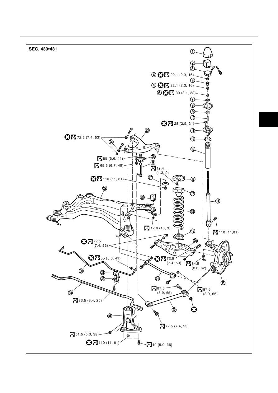
REAR SUSPENSION ASSEMBLY
RSU-7
C
D
F
G
H
I
J
K
L
M
A
B
RSU
Components
NES000HO
PEIA0097E