Infiniti Q45. Manual - part 776
 

  Index      Infiniti     Infiniti Q45 - service repair manual 2006 year


Search            copyright infringement  


Content   ..  774  775  776  777   ..


Infiniti Q45. Manual - part 776


PREPARATION

RSU-3

C

D

F

G

H

I

J

K

L

M

A

B

RSU

PREPARATION

PFP:00002

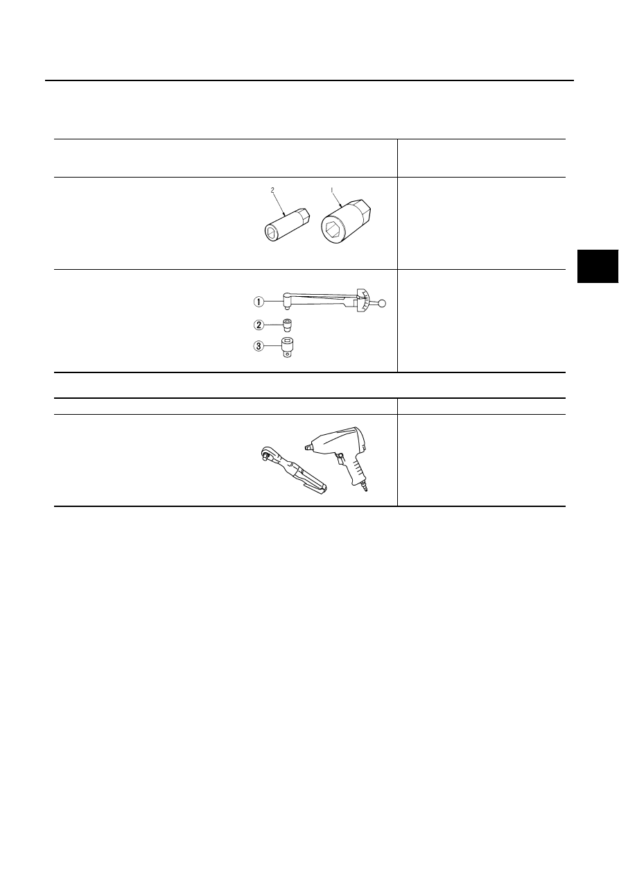
Special Service Tools (SST)

NES0006H

The actual shapes of Kent-Moore tools may differ from those of special service tools illustrated here.

Commercial Service Tools

NES0006I

Tool number
(Kent-Moore No.)
Tool name

Description

KV40106400
(

—

)

Socket wrench

Removing actuator plate fixing nut
(with active damper suspension)

ST3127S000
(See J

−

25765-A)

Preload gauge
1. GG91030000
              Torque wrench (J

−

25765)

2. HT62940000 (  —  )
               Socket adapter (1/2

″

)

3. HT62900000 (  —  )
               Socket adapter (3/8

″

)

Measuring rotating torque of ball joint

ZZA1102D

NT124

Tool name

Description

Power tool

●

Removing wheel nuts

●

Removing brake caliper

●

Removing suspension component 
parts

PBIC0190E

RSU-4

NOISE, VIBRATION AND HARSHNESS (NVH) TROUBLESHOOTING

NOISE, VIBRATION AND HARSHNESS (NVH) TROUBLESHOOTING

PFP:00003

NVH Troubleshooting Chart

NES0006J

Use chart below to help you find the cause of the symptom. If necessary, repair or replace these parts.

×

: Applicable

Reference page

RSU-

7

RSU-

9

—

—

—

RSU-

7

RSU-

5

RSU-

1

7


NVH in

 PR 

s

e

c

ti

o

n

.

NVH i

n

 RFD s

e

c

tio

n

.

NVH 

in

 RAX

 a

n

d

 RS

U

 s

e

c

ti

o

n

s

.

NVH 

in

 W

T

 s

e

c

ti

o

n

.

NVH 

in

 W

T

 s

e

c

ti

o

n

.

NVH i

n

 RAX s

e

c

tio

n

.

NVH in

 BR 

s

e

c

ti

o

n

.

NVH in

 PS 

s

e

c

ti

o

n

.

Possible cause and SUSPECTED PARTS

Im

pr

o

per

 i

n

st

al

la

ti

on

, 

lo

osen

ess

Sho

ck abs

or

b

e

r def

am

at

ion,

 d

a

m

age or

 d

e

fl

ec

ti

on

Bus

h

ing or

 m

oun

ti

ng det

er

io

ra

ti

on

P

a

rt

s

 in

te

rf

e

re

n

c

e

Spr

ing f

a

ti

gue

Sus

pens

io

n l

o

o

s

ene

ss

In

co

rr

ect

 w

h

e

e

l al

ignm

en

t

S

ta

b

ili

z

er

 bar

 f

a

ti

g

u

e

PROPELL

E

R SHAF

T

DIFFERENTIAL

REAR AXLE AND 

RE

AR 

SUSPENSION

TIRES

ROAD  

 W

H

E

E

L

S

D

R

IV

E

 SH

AF

T

BRAKES

STEERING

Symptom

REAR SUSPENSION

Noise

×

×

×

×

×

×

×

×

×

×

×

×

×

×

Shake

×

×

×

×

×

×

×

×

×

×

×

×

Vibration

×

×

×

×

×

×

×

×

×

×

Shimmy

×

×

×

×

×

×

×

×

×

×

Judder 

×

×

×

×

×

×

×

×

Poor quality ride or 
handling

×

×

×

×

×

×

×

×

×

×

REAR SUSPENSION ASSEMBLY

RSU-5

C

D

F

G

H

I

J

K

L

M

A

B

RSU

REAR SUSPENSION ASSEMBLY

PFP:55020

On-Vehicle Inspection and Service

NES0006K

Make sure the mounting conditions (looseness, back lash) of each of the component and component condi-
tions (wear, damage) are normal.

INSPECTION OF SUSPENSION ARM BALL JOINT END PLAY

Measure axial end play by installing and moving up/down between suspension arm and axle with an iron pry
bar or something similar.

CAUTION:

Be careful not to damage ball joint boot.

SHOCK ABSORBER INSPECTION

Check shock absorber for oil leakage, damage and replace if there are.

Wheel Alignment Inspection

NES000HN

DESCRIPTION

●

Measure wheel alignment under unladen conditions. “Unladen conditions” mean that fuel, engine coolant,
and lubricant are full. Spare tire, jack, hand tools and mats are in designated positions.

PRELIMINARY CHECK

●

Check tires for improper air pressure and wear.

●

Check road wheels for runout.

●

Check wheel bearing axial end play.

●

Check suspension arm ball joint axial end play.

●

Check shock absorber operation.

●

Check each mounting point of axle and suspension for looseness and deformation.

●

Check each link, arm and member for cracks, deformation, and other damage.

●

Check vehicle posture.

GENERAL INFORMATION AND RECOMMENDATIONS

●

A four-wheel thrust alignment should be performed.

–

This type of alignment is recommended for any NISSAN/INFINITI vehicle.

–

The four-wheel “thrust” process helps ensure that the vehicle is properly aligned and the steering wheel is
centered.

–

The alignment rack itself should be capable of accepting any NISSAN/INFINITI vehicle.

–

The rack should be checked to ensure that it is level.

●

Make sure the machine is properly calibrated.

–

Your alignment equipment should be regularly calibrated in order to give correct information.

–

Check with the manufacturer of your specific equipment for their recommended Service/Calibration
Schedule.

Axial end play

: 0 mm (0 in)

RSU-6

REAR SUSPENSION ASSEMBLY

THE ALIGNMENT PROCESS

IMPORTANT:
Use only the alignment specifications listed in this Service Manual.

●

When displaying the alignment settings, many alignment machines use “indicators”: (Green/red, plus or
minus, Go/No Go). Do NOT use these indicators.

–

The alignment specifications programmed into your machine that operate these indicators may not be cor-
rect.

–

This may result in an ERROR.

●

Some newer alignment machines are equipped with an optional “Rolling Compensation” method to “com-
pensate” the sensors (alignment targets or head units). DO NOT use this “Rolling Compensation”
method.

–

Use the “Jacking Compensation Method”. After installing the alignment targets or head units, raise the
vehicle and rotate the wheels 1/2 turn both ways.

–

See Instructions in the alignment machine you're using for more information on this.

CAMBER INSPECTION

●

Measure camber of both right and left wheels with a suitable
alignment gauge and adjust in accordance with the following
procedures.

If outside the standard value, adjust with adjusting bolt on front
lower link.

NOTE:
After adjusting camber, be sure to check toe-in.

TOE-IN

If toe-in is not within the specification, adjust with adjusting bolt in
rear lower link.

CAUTION:

Be sure to adjust equally on RH and LH side with adjusting bolt.
If toe-in is not still within the specification, inspect and replace any
damaged or worn rear suspension parts.

Camber

: Refer to 

RSU-19, "SERVICE DATA 

AND SPECIFICATIONS (SDS)"

 .

SRA096A

SEIA0071E

SEIA0072E


Content   ..  774  775  776  777   ..