Infiniti Q45. Manual - part 751
POWER STEERING GEAR
PS-21
C
D
E
F
H
I
J
K
L
M
A
B
PS
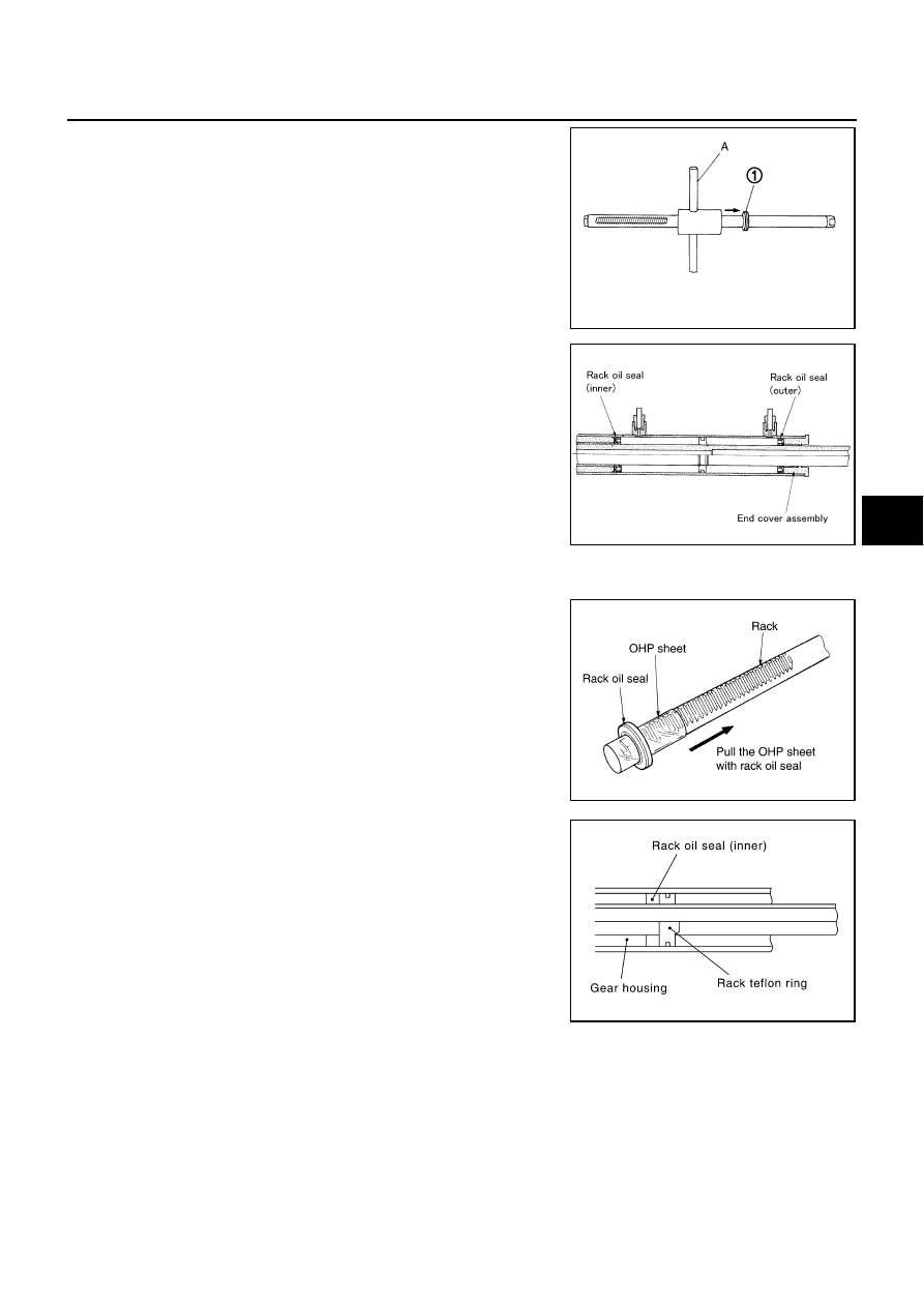
3.
Install the Tool “A” from tooth side of rack to fit rack Teflon ring
(1) on rack. Compress the ring with tool.
4.
Apply multi-purpose grease to rack oil seal. And install rack oil
seal in the following procedure. Then assemble rack assembly
to gear housing assembly.
CAUTION:
●
Never reuse the rack oil seal.
●
Install rack oil seal in a direction so that the lip of inner oil
seal and the lip of outer oil seal face each other.
●
Never damage the retainer sliding surface by the rack
assembly. Replace the gear housing assembly if dam-
aged.
●
Never damage the gear housing assembly inner wall by
the rack assembly. Gear housing assembly must be replaced if damaged because it may cause
fluid leakage.
a.
Wrap an OHP sheet [approximately 70 mm (2.76 in)
×
100 mm
(3.94 in).] Around rack assembly teeth to avoid damaging rack
oil seal (inner). Install rack oil seal over sheet. Then, pull oil seal
along with OHP sheet until they pass rack assembly teeth, and
remove OHP sheet.
b.
Insert rack oil seal (inner) into rack assembly piston (rack Teflon
ring).
c.
Push retainer to adjusting screw side by hand, and move the
rack assembly inside the gear housing assembly so that the
rack oil seal (inner) can be pressed against the gear housing
assembly.
Tool number
A: KV48104400 (
—
)
SGIA1543E
SGIA0205E
SGIA0155E
SGIA0671E