Index Infiniti Infiniti Q45 - service repair manual 2006 year
Search copyright infringement
Content .. 688 689 690 691 ..
Infiniti Q45. Manual - part 690
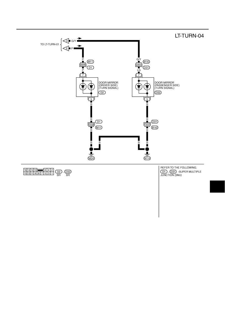
TURN SIGNAL AND HAZARD WARNING LAMPS
LT-97
C
D
E
F
G
H
I
J
L
M
A
B
LT
TKWM1500E