Infiniti Q45. Manual - part 630
REVERSE INTERLOCK DOOR MIRROR SYSTEM
GW-113
C
D
E
F
G
H
J
K
L
M
A
B
GW
3.
HARNESS CONTINUITY INSPECTION
1.
Turn ignition switch OFF.
2.
Disconnect door mirror control unit D5 (driver side), D35 (passenger side) and door mirror connector D2
(driver side), D32 (passenger side) connectors.
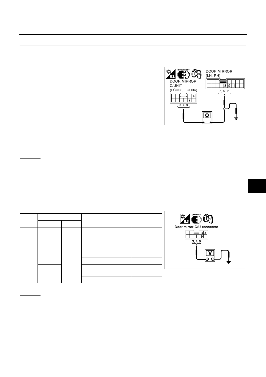
3.
Check continuity between door mirror control unit connector D5
(driver side), D35 (passenger side) terminals 3, 4, 9 and door
mirror connector D2 (driver side), D32 (passenger side) termi-
nals 8, 9, 11.
4.
Check continuity between door mirror control unit connector D5
(driver side), D35 (passenger side) terminals 3, 4, 9 and ground.
*:Wire color for passenger side door mirror and passenger side door mirror control unit.
OK or NG
OK
>> GO TO 4.
NG
>> Repair or replace harness.
4.
MIRROR MOTOR SIGNAL INSPECTION
1.
Connect door mirror control unit D5 (driver side), D35 (passenger side) and door mirror connector D2
(driver side), D32 (passenger side) connectors.
2.
Turn ignition switch ON.
3.
Check voltage between door mirror control unit connector (driver side), (passenger side) and ground.
*:Wire color for passenger side door mirror control unit
OK or NG
OK
>> Replace the door mirror motor (driver side) or (passenger side).
NG
>> Replace the door mirror control unit (driver side) or (passenger side).
3 (GY/R)(R)* – 8 (GY/R)(R)*
:Continuity should exist.
4 (BR) – 9 (BR)
:Continuity should exist.
9 (PU/W)(OR)*–11 (PU/W)(OR)*
:Continuity should exist.
3 (GY/R)(R)* – Ground
:Continuity should not exist.
4 (BR) – Ground
:Continuity should not exist.
9 (PU/W)(OR)* – Ground
:Continuity should not exist.
PIIA0203E
Con-
nector
Terminals (Wire color)
Condition
Voltage [V]
(Approx.)
(+)
(–)
D5
D35
3 (GY/R)
(R)*
Ground
When motor is actiated
(UP)
Battery voltage
When motor is not activated
0
4 (BR)
When motor is actiaged
(LEFT)
Battery voltage
When motor is not activated
0
9 (PU/W)
(OR)*
When motor is activated
(RIGHT) or (DOWN)
Battery voltage
When motor is not activated
0
PIIA3539E