Infiniti Q45. Manual - part 608


  Index      Infiniti     Infiniti Q45 - service repair manual 2006 year


Search            copyright infringement  


Content   ..  606  607  608  609   ..


Infiniti Q45. Manual - part 608


POWER WINDOW SYSTEM

GW-25

C

D

E

F

G

H

J

K

L

M

A

B

GW

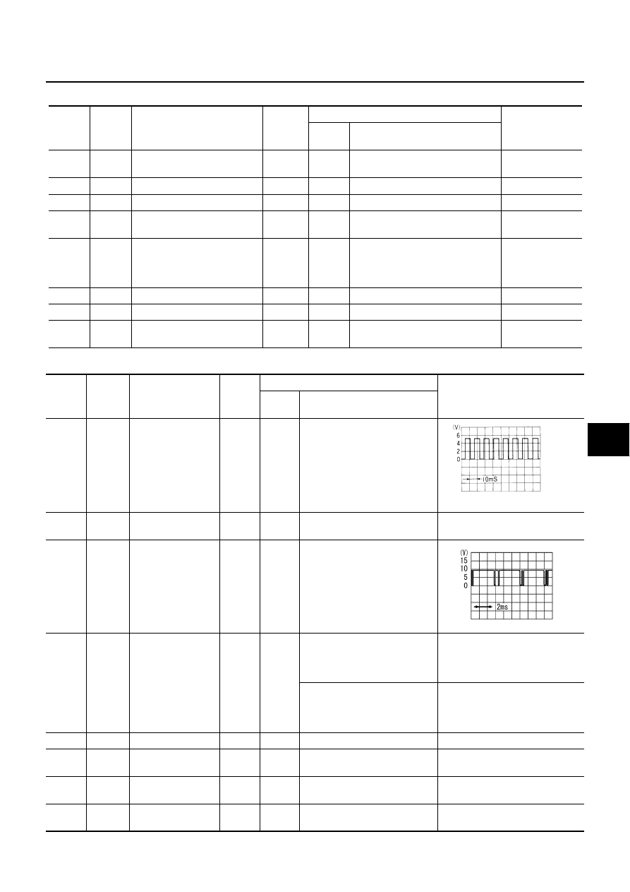
Terminals and Reference Value for BCM

NIS001L8

Terminals and Reference Value for Driver Door Control Unit

NIS000YP

TERMI-

NAL

WIRE 

COLOR

Signal name

Signal 

input/

output

Measuring condition

VOLTAGE (V)

(Approx.)

Ignition

switch

Operation condition

37

W/G

Front door switch passenger 
side

Input

OFF

Door open (ON) 

 close (OFF)


Battery voltage

56

B

Ground

ON

0

67

G/W

Data line A-3

68

W/B

Ignition switch (ON)

Input

ON

Ignition switch (ON or START posi-
tion)

Battery voltage

69

PU/W

Key switch

Input

OFF

Key Inserted in IGN key cylinder 
(ON) 

key removed from IGN key cylinder 
(OFF)

Battery voltage 

0

105

Y/L

Power source (Fuse)

Input

OFF

Battery voltage

113

B

Ground

ON

0

142

W/R

Front door switch (driver side)

Input

OFF

Door open (ON) 

 close (OFF)


Battery voltage

TERMI-

NAL

WIRE 

COLOR

Signal name

Signal 

input/

output

Measuring condition

Voltage (V)

(Approx.)

Ignition

switch

Operation condition

1

G

Encoder pulse sig-
nal

Input

ON

When power window motor 
operates

4

W

Encoder power sup-
ply

Output

ON

When ignition switch ON or 
power window timer operates

10

5

G/OR

Local communica-
tion

ON

When ignition switch ON or 
power window timer operates

7

PU

Limit switch signal

Input

ON

Driver side door window is in a 
position between fully-open and 
just before fully-closed position 
(ON)

0

Driver side door window is in a 
position between just before 
fully-closed position and fully-
closed position (OFF)

5

8

G/W

Data line A-3

9

PU/W

Door key cylinder 
unlock switch

Input

OFF

OFF (Neutral) 

 ON (Unlock)

 0

10

GY

Door key cylinder
 lock switch

Input

OFF

OFF (Neutral) 

 ON (Lock)

 0

11

L/W

Power window 
motor DOWN signal

Output

ON

When power window motor 
DOWN operates

Battery voltage

OCC3383D

SIIA0591J

GW-26

POWER WINDOW SYSTEM

Terminals and Reference Value for Passenger, Rear LH, RH Door Control Unit

NIS000YQ

(): Passenger door control unit

14

Y/G

Power source
(Fusible link)

Input

OFF

Battery voltage

15

B

Ground

ON

0

18

L/R

Power window 
motor UP signal

Output

ON

When power window motor UP 
operates

Battery voltage

TERMI-

NAL

WIRE 

COLOR

Signal name

Signal 

input/

output

Measuring condition

Voltage (V)

(Approx.)

Ignition

switch

Operation condition

TERMI-

NAL

WIRE 

COLOR

Signal name

Signal 

input/

output

Measuring condition

Voltage (V)

(Approx.)

Ignition

switch

Operation condition

4

L/W

Power window 
motor DOWN signal

Output

ON

When power window motor 
DOWN operates

Battery voltage

5

L/R

Power window 
motor UP signal

Output

ON

When power window motor 
UP operates

Battery voltage

6

Y/B

(W/R)

Power source 
(FUSE)

Input

OFF

Battery voltage

7

B

Ground

0

11

G/OR

Local communica-
tion

ON

When ignition switch ON or 
power window timer operates

15

W

Encoder power sup-
ply

Output

ON

When ignition switch ON or  
power window timer  oper-
ates

10

16

OR

(PU)

Limit switch signal

Input

ON

Door window is between 
fully-open and just before 
fully-closed position (ON)

0

Door window is between just 
before fully-closed position 
and fully-closed position 
(OFF)

5

19

G

Encoder pulse sig-
nal

Input

ON

When power window motor 
operates

SIIA0591J

OCC3383D

POWER WINDOW SYSTEM

GW-27

C

D

E

F

G

H

J

K

L

M

A

B

GW

Trouble Diagnosis Symptom Chart

NIS000YR

Check that other systems using the signal of the following systems operate normally.

Symptom

Diagnostic procedure.

Refer page

None of the power windows can be operated using any switch.

Check the following.

40A fusible link (letter H , located in fuse and 
fusible link box)

harness for open and short between BCM 
and power window main switch (LCU01).
Refer to 

LAN-7, "On Board Diagnosis"

Power window main switch (LCU01)

BCM

Driver side power window cannot be operated but other windows 
can be operated.

1. Check driver door control unit circuit.

GW-41

2. Check front power window motor (driver 
side) circuit. 

GW-30

3. Replace driver door control unit (LCU1)

EI-40

Passenger side power window cannot be operated but other win-
dows can be operated.

1. Check passenger door control unit circuit.

GW-42

2. Check front power window motor (passenger 
side) circuit.

GW-30

3. Replace passenger door control unit.

EI-40

Rear LH or RH power window cannot be operated but other win-
dows can be operated.

1. Rear door control unit (LH or RH) circuit.

GW-43

2. Check rear power window motor (LH or RH) 
circuit.

GW-31

3. Replace rear LH or RH door control unit.

EI-40

Power windows except driver’s side window cannot be operated 
using power window main switch.

1. Check communication signal circuit.

GW-28

2. Replace the power window main switch.

Anti-pinch system does not operate normally (driver side).

1. Limit switch adjusting.

GW-53

2. Check limit switch (driver side)

GW-32

3. Check encoder circuit (driver side)

GW-36

4. Door window sliding part malfunction.

A foreign material adheres to window glass 
or glass run rubber.

Glass run rubber wear or deformation.

Sash is tilted too much, or not enough.

5. Replace driver door control unit (LCU1).

EI-40

Anti-pinch system does not operate normally (passenger side).

1. Limit switch adjusting.

GW-53

2. Check limit switch (passenger side).

GW-33

3. Check encoder circuit (passenger side).

GW-38

4. Door window sliding part malfunction.

A foreign material adheres to window glass 
or glass run rubber.

Glass run rubber wear or deformation.

Sash is tilted too much, or not enough.

5. Replace passenger side door control unit.

EI-40

GW-28

POWER WINDOW SYSTEM

Check Communication Signal Circuit

NIS000YS

1. 

CHECK COMMUNICATION CIRCUIT 

1.

Turn ignition switch OFF.

2.

Disconnect driver door control unit (LCU01) and malfunctioning door control unit connector.

3.

Check continuity between driver door control unit (LCU01) connector terminal 5 and malfunctioning door
control unit connector terminal 11.

4.

Check continuity between driver door control unit (LCU01) connector terminal 5 and ground.

OK or NG

OK

>> GO TO 2.

NG

>> Repair or replace harness

Anti-pinch system does not operate normally (rear RH or LH).

1. Limit switch adjusting.

GW-53

2. Check limit switch (rear LH or RH).

GW-35

3. Check encoder circuit (rear LH or RH).

GW-39

4. Door window sliding part malfunction.

A foreign material adheres to window glass 
or glass run rubber.

Glass run rubber wear or deformation.

Sash is tilted too much, or not enough.

Power window timer function does not operate properly.

1.Check door switch.

GW-44

2. Check the following

harness for open and short between BCM 
and power window main switch (LCU01).
Refer to 

LAN-7, "On Board Diagnosis"

BCM

Symptom

Diagnostic procedure.

Refer page

Passenger door control unit

Terminals

Continuity

Driver door control unit

Passenger door control unit

Connector

Terminal

(Wire color)

Connector

Terminal

(Wire color)

D8

5 (G/OR)

D38

11 (G/OR)

Yes

Rear door control unit LH or RH

Terminals

Continuity

Driver door control unit

Rear LH or RH door control unit 

Connector

Terminal

(Wire color)

Connector

Terminal

(Wire color)

D8

5 (G/OR)

D58 (LH)

D78 (RH)

11 (G/OR)

Yes

 5 (G/OR) – Ground

: Continuity should not exist.

PIIB0301E


Content   ..  606  607  608  609   ..