Infiniti Q45. Manual - part 585
FRONT SUSPENSION ASSEMBLY
FSU-7
C
D
F
G
H
I
J
K
L
M
A
B
FSU
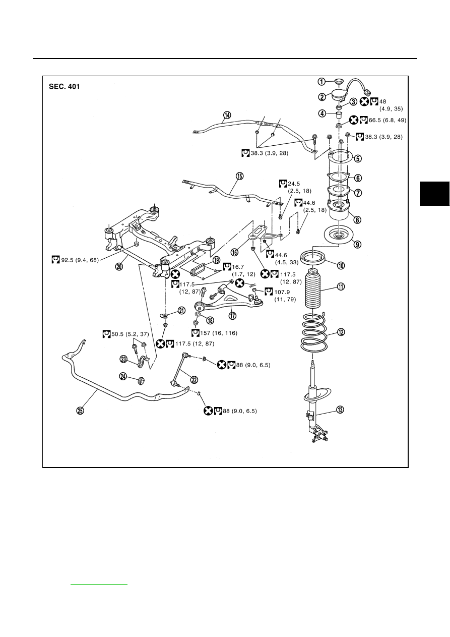
Components
NES000HM
1.
Cap (Without active damper
suspension)
2.
Actuator assembly (With active
damper suspension)
3.
Nut (With active damper suspen-
sion)
4.
Actuator plate (With active damper
suspension)
5.
Tower bar bracket
6.
Spacer
7.
Strut mounting insulator bracket
8.
Strut mounting insulator assembly
9.
Spring upper seat
10. Upper rubber seat
11. Bound bumper
12. Coil spring
13. Strut assembly
14. Tower bar
15. Front cross bar
16. Member stay
17. Suspension arm
18. Washer
19. Dynamic damper
20. Front suspension member
21. Rebound stopper
22. Stabilizer connecting rod
23. Stabilizer clamp
24. Stabilizer bushing
25. Stabilizer bar
Refer to
, for the symbols in the figure.
PEIA0065E