Infiniti Q45. Manual - part 583


  Index      Infiniti     Infiniti Q45 - service repair manual 2006 year


Search            copyright infringement  


Content   ..  581  582  583  584   ..


Infiniti Q45. Manual - part 583


FUEL TANK

FL-9

C

D

E

F

G

H

I

J

K

L

M

A

FL

6.

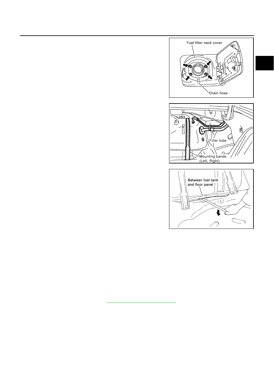
Remove fuel filler neck cover.

7.

Remove filer tube.

8.

Remove fuel tank mounting band mounting bolts.

9.

If the bottom of fuel tank hard contacts to remove from trunk
floor panel, insert a wood block or something similar to separate
them.

CAUTION:

Use a shop cloth or others like that to avoid deformation or
damage to fuel tank and the floor panel.

10. Pull fuel tank backwards to remove.

INSTALLATION

Note the following, and install in the reverse order of removal.

Push mounting band pin to the vehicle side securely.

Referring to the mating marks marked during removal, install fuel tubes and EVAP tubes and fix to the
clamps securely. 

Before fixing fuel tank, temporarily install filler tube.

CAUTION:

Use genuine filler tube mounting bolts or equivalent. Make sure to tighten them to the specified
torque.

To connect quick connector, refer to 

FL-3, "Removal and Installation"

 .

INSPECTION AFTER INSTALLATION

After installing tubes, make sure there is no fuel leakage at connections in the following steps.

Apply fuel pressure to fuel lines with turning ignition switch “ON” (with engine stopped). Then check for
fuel leaks at connections.

Start engine and rev it up and check for fuel leaks at connections.

PBIC2131E

PBIC0169E

PBIC1196E

FL-10

SERVICE DATA AND SPECIFICATIONS (SDS)

SERVICE DATA AND SPECIFICATIONS (SDS)

PFP:00030

Standard and Limit

NBS0028L

Fuel tank capacity

Approx. 80 

  (21-1/8 US gal, 17-5/8 Imp gal)

Fuel recommendation

Refer to 

GI-5

FSU-1

FRONT SUSPENSION

E  SUSPENSION

CONTENTS

C

D

F

G

H

I

J

K

L

M

SECTION 

FSU

A

B

FSU

FRONT SUSPENSION

PRECAUTION ............................................................ 2

Caution ..................................................................... 2

PREPARATION ........................................................... 3

Special Service Tools (SST) ..................................... 3
Commercial Service Tools ........................................ 3

NOISE, VIBRATION AND HARSHNESS (NVH) 
TROUBLESHOOTING ................................................ 4

NVH Troubleshooting Chart  ..................................... 4

FRONT SUSPENSION ASSEMBLY ........................... 5

On-Vehicle Inspection and Service  .......................... 5

INSPECTION LOWER BALL JOINT END PLAY 

..... 5

STRUT INSPECTION  ........................................... 5

Wheel Alignment Inspection ..................................... 5

DESCRIPTION ...................................................... 5
PRELIMINARY CHECK  ........................................ 5
GENERAL INFORMATION AND RECOMMEN-
DATIONS .............................................................. 5
THE ALIGNMENT PROCESS  .............................. 6
INSPECTION OF CAMBER, CASTER AND 
KINGPIN INCLINATION ANGLES  ........................ 6

Components ............................................................. 7

COIL SPRING AND STRUT  ....................................... 8

Removal and Installation  .......................................... 8

REMOVAL ............................................................. 8

INSTALLATION ..................................................... 9

Disassembly and Assembly .................................... 10

DISASSEMBLY ................................................... 10
INSPECTION AFTER DISASSEMBLY ................ 11
ASSEMBLY ......................................................... 11

SUSPENSION ARM .................................................. 13

Removal and Installation  ........................................ 13

REMOVAL ........................................................... 13
INSPECTION AFTER REMOVAL  ....................... 13
INSTALLATION ................................................... 14

STABILIZER BAR  ..................................................... 15

Removal and Installation  ........................................ 15

REMOVAL ........................................................... 15
INSPECTION AFTER REMOVAL  ....................... 15
INSTALLATION ................................................... 15

FRONT SUSPENSION MEMBER ............................. 16

Removal and Installation  ........................................ 16

REMOVAL ........................................................... 16
INSPECTION AFTER REMOVAL  ....................... 16
INSTALLATION ................................................... 16

SERVICE DATA AND SPECIFICATIONS (SDS)  ...... 17

Wheel Alignment (Unladen*)  .................................. 17
Ball Joint  ................................................................. 17
Wheelarch Height (Unladen*) ................................. 17

FSU-2

PRECAUTION

PRECAUTION

PFP:00001

Caution

NES00061

When installing rubber bushings, the final tightening must be carried out under unladen conditions with
tires on ground. Oil will shorten the life of rubber bushings. Be sure to wipe off any spilled oil.

Unladen conditions mean that fuel, engine coolant and lubricant are full. A spare tire, a jack, hand tools
and mats are in designated positions.

After servicing suspension parts, be sure to check wheel alignment.

Self-lock nuts are not reusable. Always use new ones when installing. Since new caulking nuts are pre-
oiled, tighten as they are.


Content   ..  581  582  583  584   ..