Infiniti Q45. Manual - part 550


  Index      Infiniti     Infiniti Q45 - service repair manual 2006 year


Search            copyright infringement  


Content   ..  548  549  550  551   ..


Infiniti Q45. Manual - part 550


AIR CLEANER AND AIR DUCT

EM-17

C

D

E

F

G

H

I

J

K

L

M

A

EM

AIR CLEANER AND AIR DUCT

PFP:16500

Removal and Installation

NBS001OJ

REMOVAL

1.

Remove engine cover with power tool. Refer to 

EM-13, "ENGINE ROOM COVER"

 .

2.

Remove air cleaner cover. Refer to 

EM-13, "ENGINE ROOM COVER"

 .

3.

Disconnect harness connector from mass air flow sensor.

4.

Remove air duct (inlet), air duct and air cleaner case assembly disconnecting their joints.

Add marks as necessary for easier installation.

5.

Remove mass air flow sensor from air cleaner case, as necessary.

CAUTION:

Handle mass air flow sensor with the following cares.

Do not shock it.

Do not disassemble it.

Do not touch its sensor.

INSTALLATION

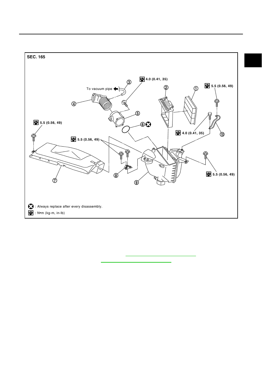
Note the following, and install in the reverse order of removal.

Align marks. Attach each joint. Screw clamps firmly.

1.

Air cleaner filter

2.

Holder

3.

Vacuum hose

4.

Air duct 

5.

Mass air flow sensor

6.

O-ring

7.

Air duct (inlet)

8.

Bracket

9.

Air cleaner case

10.

Bracket

PBIC2772E

EM-18

AIR CLEANER AND AIR DUCT

INSPECTION AFTER REMOVAL

Inspect air duct and resonator assembly for check or tear

If anything found, replace air duct and resonator assembly.

CHANGING AIR CLEANER FILTER
Removal

1.

Remove air cleaner cover. Refer to 

EM-13, "ENGINE ROOM COVER"

 .

2.

Unhook clips and lift up holder with air cleaner filter.

3.

Remove air cleaner filter.

Installation

Install in the reverse order of removal.

INTAKE MANIFOLD

EM-19

C

D

E

F

G

H

I

J

K

L

M

A

EM

INTAKE MANIFOLD

PFP:14003

Removal and Installation

NBS001OK

1.

PCV tube

2.

PCV hose

3.

EVAP canister purge volume control 
solenoid valve bracket

4.

EVAP canister purge volume control 
solenoid valve

5.

EVAP hose

6.

EVAP tube

7.

Vacuum gallery

8.

Engine cover front bracket

9.

EVAP hose

PBIC4180E

EM-20

INTAKE MANIFOLD

REMOVAL

WARNING:

To avoid the danger of being scalded, do not drain engine coolant when engine is hot.

1.

Remove engine cover (with power tool), air duct (inlet), air cleaner cover and battery cover. Refer to 

EM-

13, "Removal and Installation"

 .

2.

Release fuel pressure. Refer to 

EC-80, "FUEL PRESSURE RELEASE"

 .

3.

Remove air duct and air cleaner case assembly. Refer to 

EM-17, "Removal and Installation"

 .

4.

Drain engine coolant when engine is cooled. Refer to 

CO-8, "Changing Engine Coolant"

 .

5.

Disconnect fuel feed hose quick connector on engine side.
Refer to 

EM-32, "FUEL INJECTOR AND FUEL TUBE"

 . 

6.

Remove or disconnect intake manifold (upper), harnesses, brackets, vacuum hose, water gallery, vacuum
gallery and PCV hose and tube.

Add mating marks as necessary for easier installation.

7.

Remove electric throttle control actuator as follows:

a.

Disconnect harness connector.

b.

Loosen mounting bolts diagonally.

CAUTION:

Handle carefully to avoid any shock to electric throttle control actuator.

Do not disassemble.

8.

Disconnect water hoses from water gallery.

9.

Remove intake manifold adapter.

10. Remove fuel injectors and fuel tube assembly. Refer to 

EM-32, "Removal and Installation"

 .

11. Loosen bolts in the reverse order of figure to remove intake

manifold (upper) with power tool.

10. EVAP service port

11. Engine cover rear bracket

12. VIAS control solenoid valve

13. Water gallery

14. Gasket

15. Intake manifold (lower)

16. Water hose

17. Electric throttle control actuator

18. Intake manifold adapter

19. Engine cover rear bracket

20. Intake manifold (upper)

21. Vacuum tank 

SBIA0353E

PBIC0014E


Content   ..  548  549  550  551   ..