Index Infiniti Infiniti Q45 - service repair manual 2006 year
Search copyright infringement
Content .. 513 514 515 516 ..
Infiniti Q45. Manual - part 515
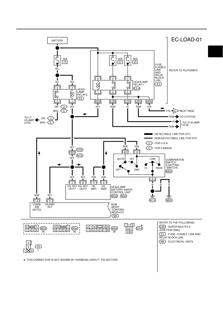
ELECTRICAL LOAD SIGNAL
EC-699
C
D
E
F
G
H
I
J
K
L
M
A
EC
Wiring Diagram
NBS0027L
TBWM1258E