Infiniti Q45. Manual - part 476
DTC P1225 TP SENSOR
EC-543
C
D
E
F
G
H
I
J
K
L
M
A
EC
Diagnostic Procedure
NBS00229
1.
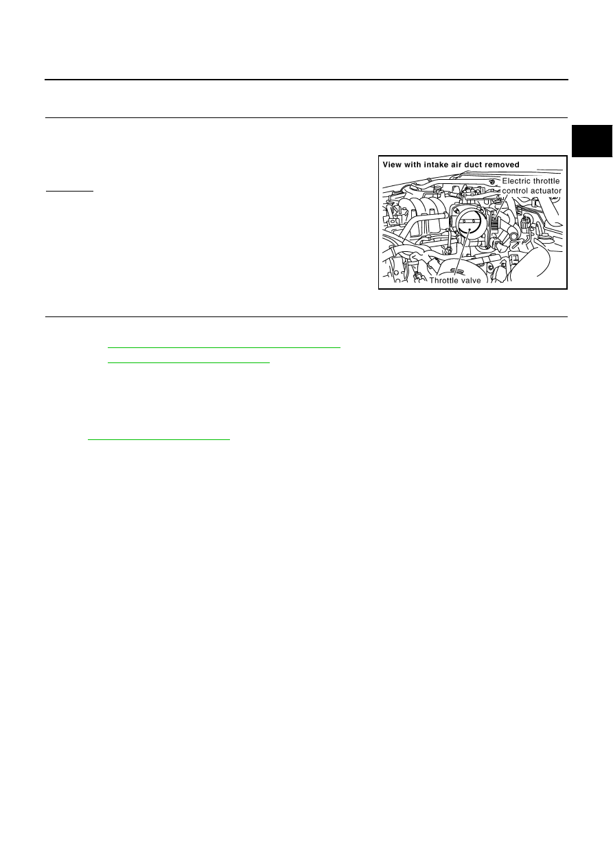
CHECK ELECTRIC THROTTLE CONTROL ACTUATOR VISUALLY
1.
Turn ignition switch OFF.
2.
Remove the intake air duct.
3.
Check if foreign matter is caught between the throttle valve and
the housing.
OK or NG
OK
>> GO TO 2.
NG
>> Remove the foreign matter and clean the electric throttle
control actuator inside.
2.
REPLACE ELECTRIC THROTTLE CONTROL ACTUATOR
1.
Replace the electric throttle control actuator.
2.
Perform
EC-78, "Throttle Valve Closed Position Learning"
3.
Perform
EC-78, "Idle Air Volume Learning"
>> INSPECTION END
Removal and Installation
NBS0022A
ELECTRIC THROTTLE CONTROL ACTUATOR
Refer to
PBIB2439E