Infiniti Q45. Manual - part 337


  Index      Infiniti     Infiniti Q45 - service repair manual 2006 year


Search            copyright infringement  


Content   ..  335  336  337  338   ..


Infiniti Q45. Manual - part 337


VOICE ACTIVATED CONTROL SYSTEM

DI-215

C

D

E

F

G

H

I

J

L

M

A

B

DI

2. 

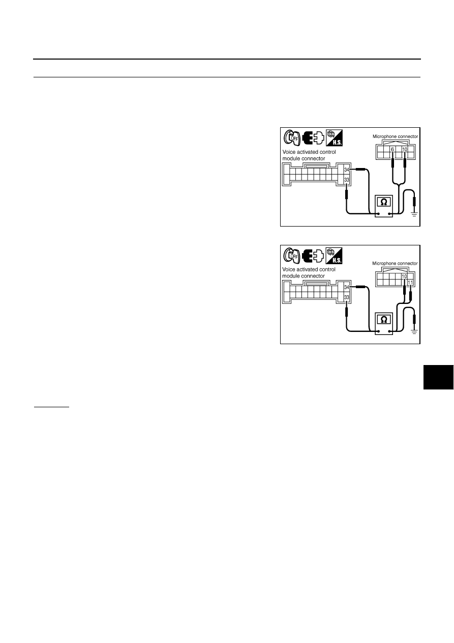
CHECK MICROPHONE CIRCUIT

1.

Turn ignition switch OFF.

2.

Disconnect voice activated control module connector and microphone connector.

3.

Check the following.

With NAVI

Continuity between voice activated control module harness con-
nector B69 terminal 34 and microphone harness connector R25
terminal 10.

Continuity between voice activated control module harness con-
nector B69 terminal 33 and microphone connector R25 terminal
6.

Without NAVI

Continuity between voice activated control module harness con-
nector B69 terminal 34 and microphone harness connector R10
terminal 10.

Continuity between voice activated control module harness con-
nector B69 terminal 33 and microphone connector R10 terminal
11.

4.

Check continuity between voice activated control module harness connector B69 terminals 33, 34 and
ground.

OK or NG

OK

>> GO TO 3.

NG

>> Repair harness or connector.

34 – 10

: Continuity should exist.

33 – 6

: Continuity should exist.

PKIC4895E

34 – 10

: Continuity should exist.

33 – 11

: Continuity should exist.

PKIC8361E

33 – Ground

: Continuity should not exist.

34 – Ground

DI-216

VOICE ACTIVATED CONTROL SYSTEM

3. 

CHECK MICROPHONE SIGNAL

1.

Connect voice activated control module connector and micro-
phone connector.

2.

Turn ignition switch ON.

3.

Speak to microphone and check voltage signal between voice
activated control module connector B69 terminals 34 and 33.

OK or NG

OK

>> Replace voice activated control module.

NG

>> Replace microphone.

No Guide Sound or Beeps

NKS001EU

1. 

CHECK GUIDE SOUND SETTING

Check volume setting of voice activated control system if set as 0 (zero).

OK or NG

OK

>> GO TO 2.

NG

>> Adjust volume.

2. 

CHECK BOSE SPEAKER AMP. CIRCUIT

1.

Turn ignition switch OFF.

2.

Disconnect voice activated control module connector and BOSE
speaker amp. connector.

3.

Check continuity between voice activated control module har-
ness connector B69 terminal 25 and BOSE speaker amp. har-
ness connector B234 terminal 42.

4.

Check continuity between voice activated control module har-
ness connector B69 terminal 26 and BOSE speaker amp. har-
ness connector B234 terminal 26.

5.

Check continuity between voice activated control module harness connector B69 terminals 25, 26 and
ground.

OK or NG

OK

>> GO TO 3.

NG

>> Repair harness or connector.

34 – 33:

PKIA9794E

PKIA0356E

25 – 42

: Continuity should exist.

26 – 26

: Continuity should exist.

25 – Ground

: Continuity should not exist.

26 – Ground

PKIA9795E

VOICE ACTIVATED CONTROL SYSTEM

DI-217

C

D

E

F

G

H

I

J

L

M

A

B

DI

3. 

CHECK VOICE SIGNAL

1.

Connect voice activated control module connector and BOSE
speaker amp. connector.

2.

Turn ignition switch ON.

3.

The Speaker Adaptation (SA) mode ON and voice guide signal
sent out, check voltage signal between voice activated control
module harness connector B69 terminals 25, 26 and 23.

OK or NG

OK

>> Replace BOSE speaker amp.

NG

>> Replace voice activated control module.

Voice Activated Control System Not Starting PTT Switch Pushed ON

NKS001EV

1. 

CHECK PTT SWITCH OPERATION

Check PTT switch operation with self-diagnosis of multifunction switch. Refer to 

DI-136, "Multifunction Switch

Self-Diagnosis Function"

 .

OK or NG

OK

>> GO TO 2.

NG

>> Replace steering switch.

2. 

CHECK MULTIFUNCTION SWITCH AND VOICE ACTIVATED CONTROL MODULE

Start self-diagnosis mode. Refer to 

DI-126, "On Board Self-Diagnosis Function (Without CONSULT-II)"

 .

Does self-diagnosis mode start?

YES

>> GO TO 3.

NO

>> Replace multifunction switch.

3. 

CHECK VOICE ACTIVATED CONTROL MODULE

Check voice activated control module with self-diagnosis mode started in previous step 2.

OK or NG

OK

>>

Replace AV and NAVI control unit (with NAVI).

Replace AV control unit (without NAVI).

NG

>> GO TO 4.

4. 

CHECK POWER SUPPLY AND GROUND CIRCUIT

Check power supply and ground circuit of voice activated control module. Refer to 

DI-213, "Power Supply and

Ground Circuit Inspection"

 .

OK or NG

OK

>> GO TO 5.

NG

>> Repair harness or connector.

26 – 23:
25 – 23:

PKIA9796E

PKIA0355E

DI-218

VOICE ACTIVATED CONTROL SYSTEM

5. 

CHECK AV COMMUNICATION LINE

1.

Turn ignition switch OFF.

2.

Disconnect voice activated control module connector and AV and NAVI control unit (with NAVI) connector,
or AV control unit (without NAVI) connector. 

3.

Check the following.

With NAVI

Without NAVI

OK or NG

OK

>> Replace voice activated control module.

NG

>> Repair harness or connector.

Audio Not Muted with PTT Switch Pushed ON 

NKS001EW

1. 

CHECK AUDIO UNIT CIRCUIT

1.

Turn ignition switch OFF.

2.

Disconnect voice activated control module connector and Audio
unit connector.

3.

Check continuity between voice activated control module har-
ness connector B69 terminal 27 and Audio unit harness connec-
tor M87 terminal 9.

4.

Check continuity between voice activated control module har-
ness connector B69 terminal 27 and ground.

OK or NG

OK

>> GO TO 2.

NG

>> Repair harness or connector.

Terminals

Continuity

Connector

Terminal

Connector

Terminal

B71

35

B29

48

Yes

36

47

Yes

37

46

Yes

35

46

No

36

46

No

PKIA9797E

Terminals

Continuity

Connector

Terminal

Connector

Terminal

B71

35

M50

50

Yes

36

49

Yes

37

51

Yes

35

51

No

36

51

No

PKIA9798E

27 – 9

: Continuity should exist.

27 – Ground

: Continuity should not exist.

PKIA9799E


Content   ..  335  336  337  338   ..