Infiniti Q45. Manual - part 308
LANE DEPARTURE WARNING SYSTEM
DI-99
C
D
E
F
G
H
I
J
L
M
A
B
DI
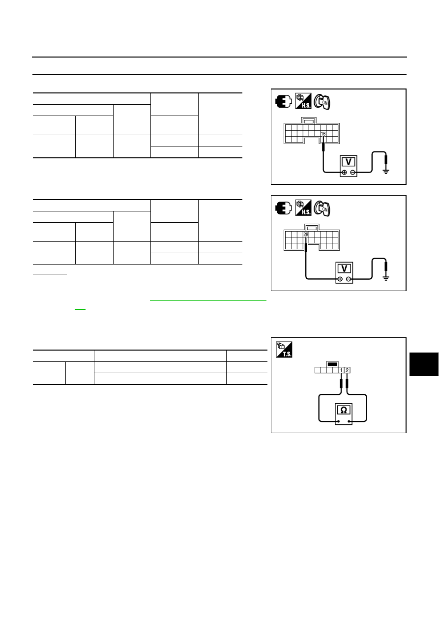
3.
CHECK VOLTAGE OF TURN SIGNAL
Check voltage between ICC unit harness connector and ground.
OK or NG
OK
>> Replace ICC unit.
NG
>> Repair harness between ICC unit and combination
Electrical Component Inspection
NKS002CD
LDW SWITCH
Check continuity between terminals 1 and 2.
Terminals
Condition
Voltage
(Approx.)
(+)
(–)
ICC unit
connector
Terminal
Turn signal
lamp (RH):
B243
16
Ground
Illuminate
12 V
Not illuminate
0 V
PKIC4901E
Terminals
Condition
Voltage
(Approx.)
(+)
(–)
ICC unit
connector
Terminal
Turn signal
lamp (LH):
B244
28
Ground
Illuminate
12 V
Not illuminate
0 V
PKIC4900E
Terminal
Condition
Continuity
1
2
When LDW switch is pushed.
Yes
When LDW switch is released.
No
PKIC4892E