Infiniti Q45. Manual - part 281
RADIATOR (ALUMINUM TYPE)
CO-17
C
D
E
F
G
H
I
J
K
L
M
A
CO
4.
Make sure that the rim is completely crimped down.
5.
Confirm that there is no leakage. Refer to
INSPECTION
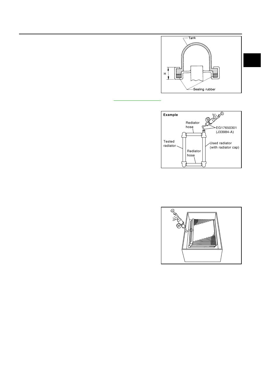
1.
Apply pressure with the radiator cap tester adapter (SST) and
the radiator cap tester (commercial service tool).
●
Provide used radiator and connect it to tested radiator using
radiator hoses as shown in the figure.
NOTE:
The used radiator should be tested beforehand to confirm it
has no leakage. If used one is not available, it is possible to
use new service part as a radiator testing tool.
WARNING:
To prevent the risk of the hose coming undone while under pressure, securely fasten it down with
a hose clamp.
CAUTION:
Attach a hose to A/T fluid cooler to seal its inlet and outlet.
2.
Check for leakage by soaking radiator in the water container
with the testing pressure applied.
Standard height “H”
: 8.0 - 8.4 mm (0.315 - 0.331 in)
SLC554A
Testing pressure
: 157 kPa (1.6 kg/cm
2
, 23 psi)
PBIC1658E
PBIC1699E