Infiniti Q45. Manual - part 279
ENGINE COOLANT
CO-9
C
D
E
F
G
H
I
J
K
L
M
A
CO
REFILLING ENGINE COOLANT
1.
Install reservoir tank if removed, and radiator drain plug.
CAUTION:
Be sure to clean drain plug and install with new O-ring.
If water drain plugs on cylinder block are removed, close and tighten them. Refer to
2.
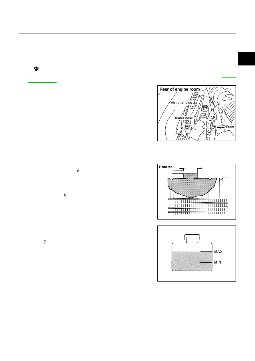
Remove air relief plug on heater hose.
3.
Fill radiator and reservoir tank to specified level.
●
Use Genuine Nissan Long life Antifreeze/Coolant or equivalent mixed with water (distilled or
demineralized). Refer to
MA-10, "RECOMMENDED FLUIDS AND LUBRICANTS"
.
●
Pour engine coolant through engine coolant filler neck
slowly of less than 2 (2-1/8 US qt, 1-3/4 Imp qt) a minute
to allow air in system to escape.
●
When engine coolant overflows air relief hole on heater hose,
install air relief plug.
4.
Install radiator cap.
5.
Warm up until opening thermostat and water control valve. Standard for warming-up time is approximately
10 minutes at 3,000 rpm.
●
Make sure thermostat opening condition by touching radiator hose ( lower) to see a flow of warm water.
CAUTION:
Watch water temperature gauge so as not to overheat engine.
6.
Stop engine and cool down to less than approximately 50
°
C (122
°
F).
●
Cool down using a fan to reduce the time.
●
If necessary, refill radiator up to filler neck with engine coolant.
Radiator drain plug:
: 1.17 N·m (0.12 kg-m, 10 in-lb)
PBIC0954E
Engine coolant capacity
(With reservoir tank at “MAX” level):
Approx. 10.3 (10-7/8 US qt, 9-1/8 Imp qt)
SMA182B
Reservoir tank engine coolant capacity
(At “MAX” level):
0.8 (7/8 US qt, 3/4 lmp qt)
SMA412B