Infiniti Q45. Manual - part 232


  Index      Infiniti     Infiniti Q45 - service repair manual 2006 year


Search            copyright infringement  


Content   ..  230  231  232  233   ..


Infiniti Q45. Manual - part 232


ELECTRONIC KEY SYSTEM

BL-197

C

D

E

F

G

H

J

K

L

M

A

B

BL

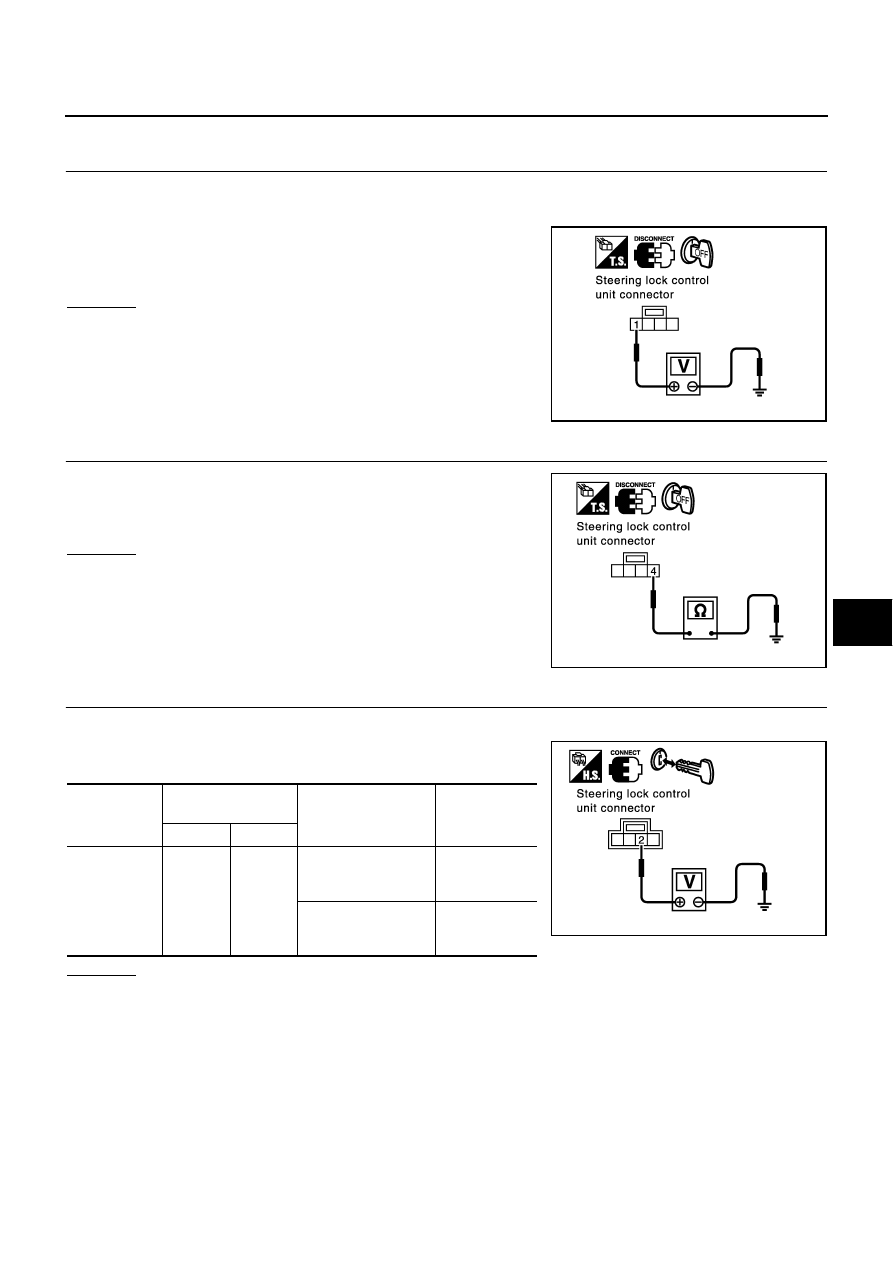
Diagnostic Procedure 2

NIS000XF

1. 

CHECK POWER SUPPLY CIRCUIT FOR STEERING LOCK CONTROL UNIT

1.

Turn ignition switch OFF.

2.

Disconnect steering lock control unit connector.

3.

Check voltage between steering lock control unit connector M69
terminal 1 and ground.

OK or NG

OK

>> GO TO 2.

NG

>> Check the following.

10A fuse [No. 6, located in the fuse block (J/B)]

Harness for open or short between fuse block and
steering lock control unit

2. 

CHECK GROUND CIRCUIT FOR STEERING LOCK CONTROL UNIT

Check voltage continuity steering lock control unit connector M69
terminal 4 and ground.

OK or NG

OK

>> GO TO 3.

NG

>> Repair or replace harness.

3. 

CHECK ELECTRONIC KEY INSERT SIGNAL 2

1.

Connect steering lock control unit connector.

2.

Check voltage between steering lock control unit connector and
ground.

OK or NG

OK

>> GO TO 4.

NG

>> Check harness for open or short between key switch and steering lock control unit.

1 (Y/G) – Ground

: Battery voltage.

PIIA3130E

4 (B) – Ground

: Continuity should exist.

PIIA3131E

Connector

Terminals

(Wire color)

Condition

Voltage (V)

(Approx.)

(+)

(–)

M69

2 (PU/W)

Ground

Electronic key 
removed from ignition 
key cylinder

0

Electronic key 
inserted in ignition cyl-
inder

Battery voltage

PIIA3132E

BL-198

ELECTRONIC KEY SYSTEM

4. 

CHECK STEERING LOCK CONTROL UNIT

Insert the electronic key into the ignition key cylinder, and immedi-
ately check voltage between steering control unit connector and
ground.

OK or NG

OK

>> Replace steering lock control unit.

NG

>>

Replace NATS IMMU.

Check harness for open or short between NATS IMMU and steering lock control unit.

Diagnostic Procedure 3

NIS000XG

1. 

CHECK SECURITY INDICATOR POWER SUPPLY CIRCUIT

1.

Turn ignition switch OFF.

2.

Disconnect the multifunction switch (security indicator lamp) connector.

3.

Check voltage between multifunction switch (security indicator
lamp) connector M83 terminal 20 and ground.

OK or NG

OK

>> GO TO 2.

NG

>> Check harness for open or short between fuse block

and multifunction switch (security indicator lamp).

2. 

CHECK SECURITY INDICATOR GROUND CIRCUIT

1.

Disconnect the NATS IMMU connector.

2.

Check continuity between multifunction switch (security indicator
lamp) connector M83 terminal 19 and NATS IMMU connector
M32 terminal 15.

3.

Check continuity between NATS IMMU harness connector M32
terminal 15 and ground.

OK or NG

OK

>> GO TO 3.

NG

>> Repair or replace harness.

Connector

Terminals

(Wire color)

Condition

Voltage (V)

(Approx.)

(+)

(–)

M69

3 (L)

Ground

Insert electronic key into 
ignition key cylinder.

 Pointer of tester 
should move.

PIIA3133E

 20 (Y/G) – Ground

: Battery voltage.

PIIA3134E

19 (G) – 15 (G)

: Continuity should exist.

15 (G) – Ground

: Continuity should not exist.

PIIA3135E

ELECTRONIC KEY SYSTEM

BL-199

C

D

E

F

G

H

J

K

L

M

A

B

BL

3. 

CHECK SECURITY INDICATOR GROUND SIGNAL

1.

Connect NATS IMMU connector.

2.

Check continuity between NATS IMMU connector M32 terminal
15 and ground.

OK or NG

OK

>> Replace multifunction switch (security indicator lamp).

NG

>> Replace NATS IMMU

15 (G) – Ground

: Continuity should exist intermit-
tently.

PIIA3136E

BL-200

IVIS (INFINITI VEHICLE IMMOBILIZER SYSTEM-NATS)

IVIS (INFINITI VEHICLE IMMOBILIZER SYSTEM-NATS)

PFP:28591

Component Parts and Harness Connector Location

NIS000XH

NOTE:
If customer reports a “No start” condition, request ALL ELECTRONIC KEY to be brought to the Dealer in case
of a NATS malfunction.

System Description

NIS000XI

IVIS (Infinity Vehicle Immobilizer System – NATS) has the following immobilizer functions:

Since only IVIS (NATS) electronic keys, whose ID numbers. have been registered into the ECM and NATS
IMMU of IVIS (NATS), allow the engine to run, operation of a stolen vehicle without a IVIS (NATS) regis-
tered electronic key is prevented by IVIS (NATS).
IVIS (NATS) will immobilize the engine if someone tries to start it without the registered electronic key of
IVIS (NATS).

All of the originally supplied electronic key IDs (except for card key and emergency key) have been IVIS
(NATS) registered. If requested by the vehicle owner, a maximum of four key IDs can be registered into
the IVIS (NATS) components.

The security indicator blinks when the ignition switch is in “OFF” or “ACC” position. Therefore, IVIS
(NATS) warns outsiders that the vehicle is equipped with the anti-theft system.

When IVIS (NATS) detects any malfunctions, the security indicator lamp lights up while electronic key is in
the “ON” position.

IVIS (NATS) trouble diagnoses, system initialization and additional registration of other IVIS (NATS) elec-
tronic key IDs must be carried out using CONSULT-II hardware and CONSULT-II IVIS (NATS) software.
When IVIS (NATS) initialization has been completed, the ID of the inserted electronic key is automatically
IVIS (NATS) registered. Then, if necessary, additional registration of IVIS (NATS) electronic key IDs can
be carried out.
Regarding the procedures of IVIS (NATS) initialization and IVIS (NATS) electronic key ID registration,
refer to CONSULT-II operation manual, IVIS/NVIS.

PIIB2118E


Content   ..  230  231  232  233   ..