Infiniti Q45. Manual - part 200
REMOTE KEYLESS ENTRY SYSTEM
BL-69
C
D
E
F
G
H
J
K
L
M
A
B
BL
Terminal and Reference Value for Driver Door Control Unit (LCU01)
NIS000UI
33
W
Door switch rear LH
Input
Door close (OFF)
→
Door open
(ON)
Battery voltage
→
0
37
W/G
Front door switch passenger
side
Input
Door close (OFF)
→
Door open
(ON)
Battery voltage
→
0
44
Y
Remote keyless entry
receiver
(Ground)
—
—
0
56
B
Ground
—
—
0
60
L/OR
Ignition switch (ACC)
Input
Ignition switch (ACC or ON position)
Battery voltage
67
G/W
Data line A-3
Input/
output
—
—
69
PU/W
Key switch
Input
Key Inserted in IGN key cylinder
(ON)
→
key removed from IGN key cylinder
(OFF)
Battery voltage
→
0
105
Y/L
Power source (Fuse)
Input
—
Battery voltage
109
LG
Trunk lid opener cancel
switch
Input
Trunk lid opener cancel switch ON
→
OFF
Battery voltage
→
0
113
B
Ground
—
—
0
127
G/W
Horn relay
Input
When panic alarm is operated using
electronic key. (OFF
→
ON)
Battery voltage
→
0
142
W/R
Front door switch driver side
Input
Door close (OFF)
→
Door open
(ON)
Battery voltage
→
0
143
W/L
Door switch rear RH
Input
Door close (OFF)
→
Door open
(ON)
Battery voltage
→
0
TER-
MINAL
WIRE
COLOR
ITEM
Signal
input/
output
CONDITION
VOLTAGE (V)
(Approx.)
TER-
MINAL
WIRE
COLOR
ITEM
Siganal
input/
output
CONDITION
VOLTAGE (V)
(Approx.)
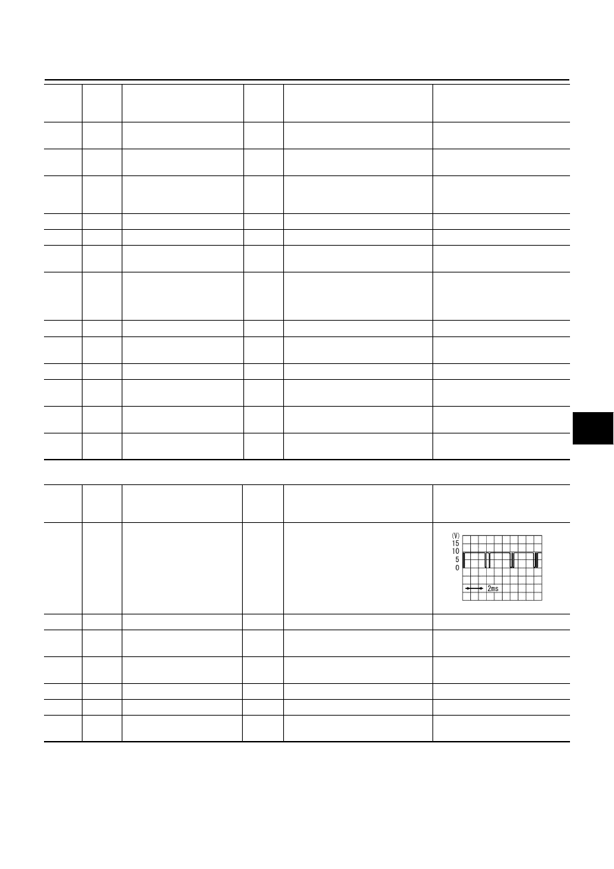
5
G/OR
Local data line
Input
—
6
G/Y
Door unlock sensor
Input
OFF (Locked)
→
ON (Unlocked)
5
→
0
8
G/W
Data line A-3
Input/
output
—
—
12
BR
Driver door lock actuator
(Unlock)
Output
Door lock & unlock switch
(Free
→
Unlock)
0
→
Battery voltage
→
0
14
Y/G
Power source (C/B)
Input
—
Battery voltage
15
B
Ground
—
—
0
17
LG
Driver door lock actuator
(Lock)
Output
Door lock & unlock switch
(Free
→
Lock)
0
→
Battery voltage
→
0
SIIA0591J