Infiniti Q45. Manual - part 131


  Index      Infiniti     Infiniti Q45 - service repair manual 2006 year


Search            copyright infringement  


Content   ..  129  130  131  132   ..


Infiniti Q45. Manual - part 131


TROUBLE DIAGNOSIS

ATC-119

C

D

E

F

G

H

I

K

L

M

A

B

ATC

3. 

CHECK INTAKE SENSOR

Refer to 

ATC-119, "Intake Sensor"

 .

OK or NG

OK

>> 1. Replace auto amp.

2. Go to self-diagnosis 

ATC-54, "FUNCTION CONFIRMATION PROCEDURE"

  and perform self-

diagnosis STEP-2. Confirm that code No. 20 is displayed.

NG

>> 1. Replace intake sensor.

2. Go to self-diagnosis 

ATC-54, "FUNCTION CONFIRMATION PROCEDURE"

  and perform self-

diagnosis STEP-2. Confirm that code No. 20 is displayed.

4. 

CHECK CIRCUIT CONTINUITY BETWEEN INTAKE SENSOR AND AUTO AMP.

1.

Turn ignition switch OFF. 

2.

Disconnect auto amp. connector.

3.

Check continuity between intake sensor harness connector M90
terminal 32 and auto amp. harness connector M119 terminal 1.

4.

Check continuity between auto amp. connector M119 terminal 1
and ground.

OK or NG

OK

>> 1. Replace auto amp.

2. Go to self-diagnosis 

ATC-54, "FUNCTION CONFIRMATION PROCEDURE"

  and perform self-

diagnosis STEP-2. Confirm that code No. 20 is displayed.

NG

>> Repair harness or connector.

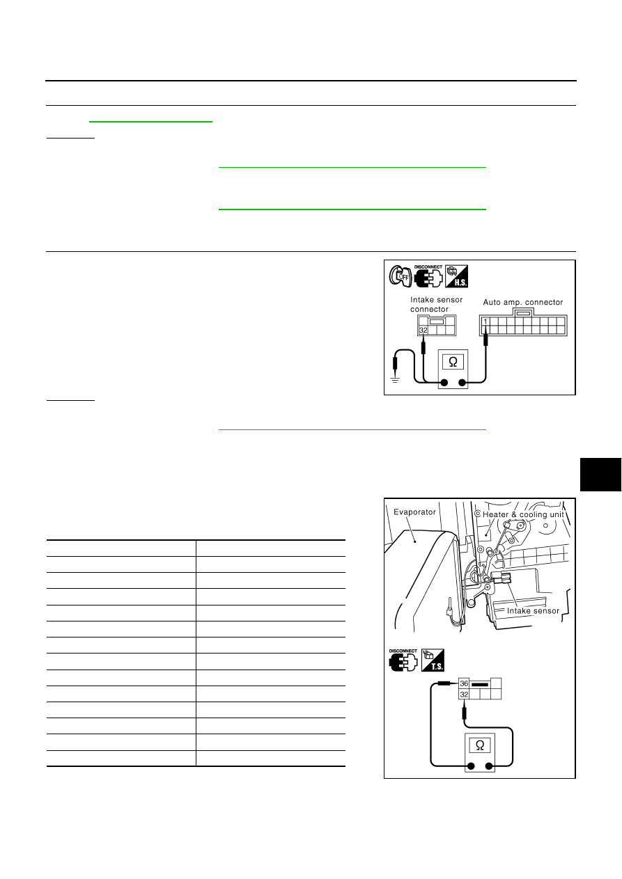
COMPONENT INSPECTION
Intake Sensor

After disconnecting intake sensor connector M90, measure resis-
tance between terminals 32 and 36 at sensor side, using the table
below.

If NG, replace intake sensor.

32 – 1

: Continuity should exist.

1 – Ground

: continuity should not exist.

RJIA3069E

Temperature 

°

C (

°

F)

Resistance k

15 (5)

12.34

10 (14)

9.62

5 (23)

7.56

0 (32)

6.00

5 (41)

4.80

10 (50)

3.87

15 (59)

3.15

20 (68)

2.57

25 (77)

2.12

30 (86)

1.76

35 (95)

1.47

40 (104)

1.23

45 (113)

1.04

RJIA3070E

ATC-120

TROUBLE DIAGNOSIS

Multiplex Communication Circuit

NJS0008Z

DIAGNOSIS PROCEDURE FOR MULTIPLEX COMMUNICATION CIRCUIT (FRONT CONTROL-
LER)

SYMPTOM:

A/C system does not come on.

A/C system cannot be controlled.

1. 

CHECK FOR AUTO AMP. OUTPUT

1.

Turn ignition switch ON.

2.

Confirm multiplex communication signal between auto amp. har-
ness connector M119 terminal 9, 20 and ground using an oscil-
loscope.

OK or NG

OK

>> GO TO 2

NG

>> Replace auto amp.

Terminals

Voltage

(+)

(

)

Auto amp. 

connector

Terminal No.

M119

9

Ground

20

RJIA3071E

RJIA0212E

HAK0363D

TROUBLE DIAGNOSIS

ATC-121

C

D

E

F

G

H

I

K

L

M

A

B

ATC

2. 

CHECK CIRCUIT CONTINUITY BETWEEN AV AND NAVI C/U (AV C/U) AND AUTO AMP.

1.

Turn ignition switch OFF.

2.

Disconnect AV and NAVI C/U (AV C/U) connector and auto amp. connector.

3.

Check continuity between AV and NAVI C/U harness connector B29 terminals 37, 39 or AV C/U harness
connector M77 terminals 44, 45 and auto amp. harness connector M119 terminals 9, 20.

OK or NG

OK

>> GO TO 3.

NG

>> Repair harness or connector.

3. 

CHECK FOR AUTO AMP. INPUT

1.

Reconnect AV and NAVI C/U (AV C/U) connector and auto amp.
connector.

2.

Turn ignition switch ON.

3.

Confirm multiplex communication signal between auto amp. har-
ness connector M119 terminal 10 and ground using an oscillo-
scope.

OK or NG

OK

>> INSPECTION END

NG

>> GO TO 4.

RJIA1312E

Terminals

Continuity

AV C/U or AV and 

NAVI C/U connector

Terminal No.

Auto amp. 

connector

Terminal No.

AV C/U

M77

44

M119

9

Yes

M77

45

M119

20 

AV and NAVI C/U

B29

37

M119

9

B29

39

M119

20 

Terminals

Voltage

(+)

(

)

Auto amp. 

connector

Terminal No. 

M119

10

Ground

RJIA3073E

RJIA0213E

ATC-122

TROUBLE DIAGNOSIS

4. 

CHECK CIRCUIT CONTINUITY BETWEEN AV AND NAVI C/U (AV C/U) AND AUTO AMP. 

1.

Turn ignition switch OFF.

2.

Disconnect AV and NAVI C/U (AV C/U) connector and auto amp. connector.

3.

Check continuity between AV and NAVI C/U harness connector B29 terminal 38 or AV C/U harness con-
nector M77 terminal 43 and auto amp. harness connector M119 terminal 10.

OK or NG

OK

>> Replace auto amp.

NG

>> Repair harness or connector.

38 – 10

: Continuity should exist.

43 – 10

: Continuity should exist.

RJIA1313E


Content   ..  129  130  131  132   ..