Infiniti Q45. Manual - part 130
TROUBLE DIAGNOSIS
ATC-115
C
D
E
F
G
H
I
K
L
M
A
B
ATC
Sunload Sensor Circuit
NJS0008X
COMPONENT DESCRIPTION
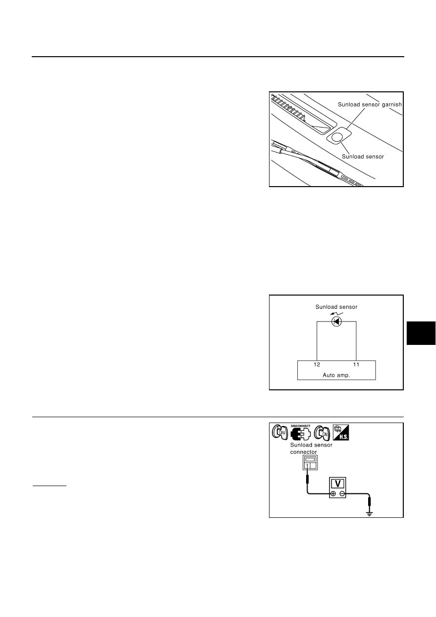
Sunload Sensor
The sunload sensor is located on the left defroster grille. It detects
sunload entering through windshield by means of a photo diode. The
sensor converts the sunload into a current value which is then input
into the auto amp.
SUNLOAD INPUT PROCESS
The auto amp. also includes a processing circuit which averages the variations in detected sunload over a
period of time. This prevents drastic swings in the ATC system operation due to small or quick variations in
detected sunload.
For example, consider driving along a road bordered by an occasional group of large trees. The sunload
detected by the sunload sensor will vary whenever the trees obstruct the sunlight. The processing circuit aver-
ages the detected sunload over a period of time, so that the (insignificant) effect of the trees momentarily
obstructing the sunlight does not cause any change in the ATC system operation. On the other hand, shortly
after entering a long tunnel, the system will recognize the change in sunload, and the system will react accord-
ingly.
DIAGNOSIS PROCEDURE FOR SUNLOAD SENSOR
SYMPTOM: Sunload sensor circuit is open or shorted. (25 or
−
25 is
indicated on auto amp. as a result of performing self-diagnosis
STEP-2.)
1.
CHECK VOLTAGE BETWEEN SUNLOAD SENSOR AND GROUND
1.
Disconnect sunload sensor connector.
2.
Turn ignition switch ON.
3.
Check voltage between sunload sensor harness connector M44
terminal 1 and ground.
OK or NG
OK
>> GO TO 2.
NG
>> GO TO 4.
RJIA0109E
RJIA0926E
1 – Ground
: Approx. 5 V
RJIA2027E