Infiniti Q45. Manual - part 51


  Index      Infiniti     Infiniti Q45 - service repair manual 2006 year


Search            copyright infringement  


Content   ..  49  50  51  52   ..


Infiniti Q45. Manual - part 51


DTC P0720 VEHICLE SPEED SENSOR A/T (REVOLUTION SENSOR)

AT-117

D

E

F

G

H

I

J

K

L

M

A

B

AT

4. 

CHECK SUB-HARNESS

1.

Remove control valve with TCM. Refer to 

AT-225, "Control Valve with TCM and A/T Fluid Temperature

Sensor 2"

 .

2.

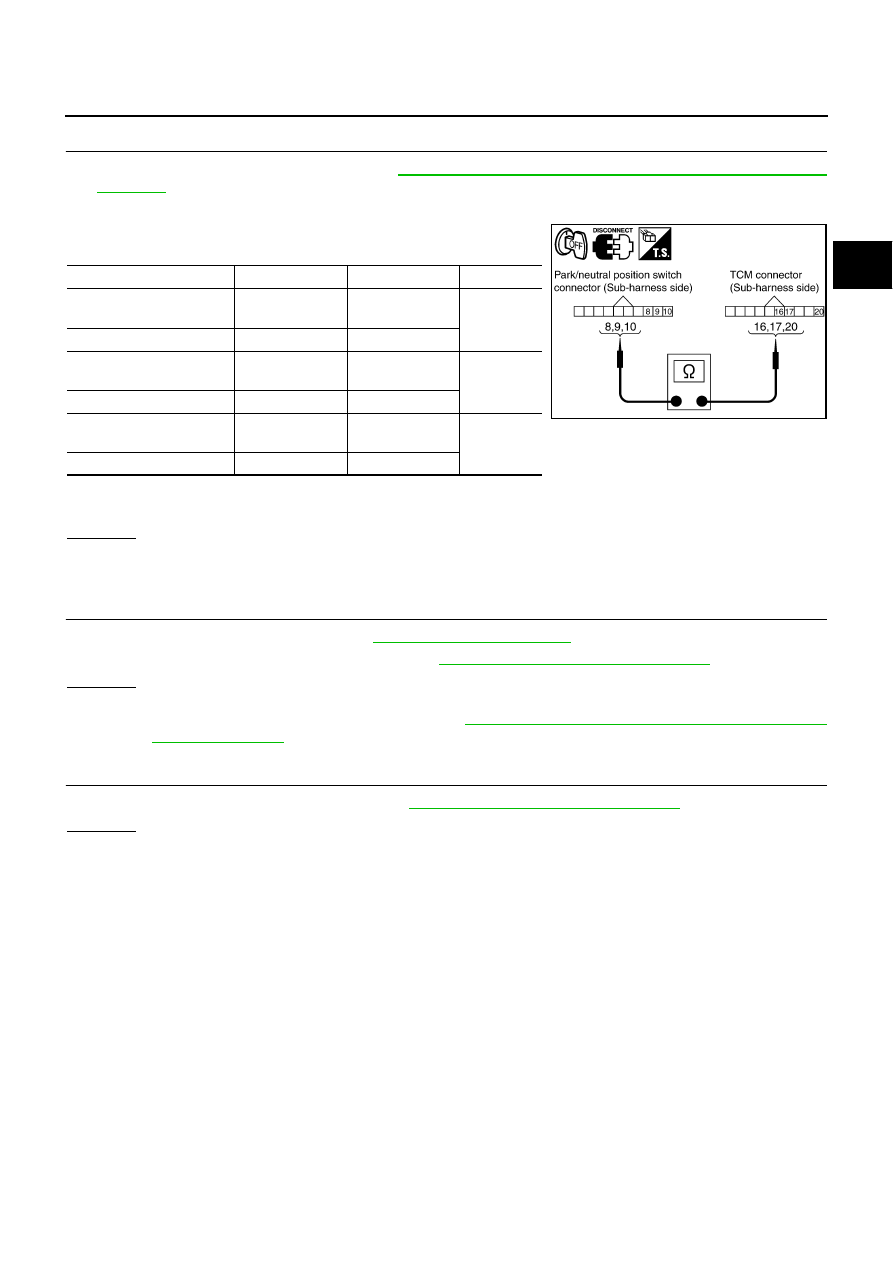
Disconnect park/neutral position switch connector and TCM connector.

3.

Check continuity between park/neutral position switch connector
terminals and TCM connector terminals.

4.

If OK, check harness for short to ground and short to power.

5.

Reinstall any part removed.

OK or NG

OK

>> GO TO 5.

NG

>> Replace open circuit or short to ground and short to power in harness or connectors.

5. 

REPLACE THE REVOLUTION SENSOR AND CHECK DTC

1.

Replace the revolution sensor. Refer to 

AT-242, "Revolution Sensor"

 .

2.

Perform “DTC Confirmation Procedure”. Refer to 

AT-113, "DTC Confirmation Procedure"

 .

OK or NG

OK

>> INSPECTION END

NG

>> Replace the control valve with TCM. Refer to 

AT-225, "Control Valve with TCM and A/T Fluid Tem-

perature Sensor 2"

 .

6. 

CHECK DTC

Perform “DTC Confirmation Procedure”. Refer to 

AT-113, "DTC Confirmation Procedure"

 .

OK or NG

OK

>> INSPECTION END

NG

>> GO TO 2.

Item

 Connector

Terminal

Continuity

Park/neutral position switch 
connector

F505

8

Yes

TCM connector 

F503

20

Park/neutral position switch 
connector

F505

9

Yes

TCM connector 

F503

17

Park/neutral position switch 
connector

F505

10

Yes

TCM connector 

F503

16

SCIA5458E

AT-118

DTC P0725 ENGINE SPEED SIGNAL

DTC P0725 ENGINE SPEED SIGNAL

PFP:24825

Description

NCS000VK

The engine speed signal is sent from the ECM to the TCM.

CONSULT-II Reference Value

NCS000VL

On Board Diagnosis Logic

NCS000VM

This is not an OBD-II self-diagnostic item.

Diagnostic trouble code “P0725 ENGINE SPEED SIG” with CONSULT-II or 16th judgement flicker without
CONSULT-II is detected when TCM does not receive the ignition signal from ECM during engine cranking
or running.

Possible Cause

NCS000VN

Harness or connectors
(ECM to TCM circuit is open or shorted.)

DTC Confirmation Procedure

NCS000VO

CAUTION:

Always drive vehicle at a safe speed.

NOTE:
If “DTC Confirmation Procedure” has been previously performed, always turn ignition switch OFF and
wait at least 10 seconds before performing the next test.
After the repair, perform the following procedure to confirm the malfunction is eliminated.

 WITH CONSULT-II

1.

Turn ignition switch ON. (Do not start engine.)

2.

Select “SELECTION FROM MENU” in “DATA MONITOR” mode
for “A/T” with CONSULT-II and check monitor “VHCL/S SE-A/T”,
“ACCELE POSI” and “SLCT LVR POSI”.

3.

Touch “START”.

4.

Start engine and maintain the following conditions for at least 10
consecutive seconds.
VHCL/S SE-A/T: 10 km/h (6 MPH) or more
ACCELE POSI: More than 1.0/8
SLCT LVR POSI: “D” position 

5.

If DTC is detected, go to 

AT-119, "Diagnostic Procedure"

 .

 WITH GST

Follow the procedure “WITH CONSULT-II”.

Item name

Condition 

Display value

ENGINE SPEED

Engine running

Closely matches the tachometer reading.

BCIA0031E

DTC P0725 ENGINE SPEED SIGNAL

AT-119

D

E

F

G

H

I

J

K

L

M

A

B

AT

Diagnostic Procedure

NCS000VP

1. 

CHECK CAN COMMUNICATION LINE

Perform the self-diagnosis. Refer to 

AT-87, "SELF-DIAGNOSTIC RESULT MODE"

 , 

AT-97, "Diagnostic Proce-

dure without CONSULT-II"

 .

Is a malfunction in the CAN communication indicated in the results?

YES

>> Check CAN communication line. Refer to 

AT-99, "DTC U1000 CAN COMMUNICATION LINE"

 .

NO

>> GO TO 2.

2. 

CHECK INPUT SIGNAL

 With CONSULT-II

1.

Start engine.

2.

Select “ECU INPUT SIGNALS” in “DATA MONITOR” mode for
“A/T” with CONSULT-II.

3.

While monitoring engine speed, check for engine speed change
corresponding to wide-open throttle position signal.

OK or NG

OK

>> GO TO 3.

NG

>> Check the ignition signal circuit.

Refer to 

EC-731, "IGNITION SIGNAL"

 .

3. 

CHECK DTC

Perform “DTC Confirmation Procedure”. Refer to 

AT-118, "DTC Confirmation Procedure"

 .

OK or NG

OK

>> INSPECTION END

NG

>> GO TO 4.

4. 

CHECK TCM POWER SUPPLY AND GROUND CIRCUIT

Check TCM power supply and ground circuit. Refer to 

AT-173, "MAIN POWER SUPPLY AND GROUND CIR-

CUIT"

 .

OK or NG

OK

>> GO TO 5.

NG

>> Repair or replace damaged parts.

5. 

DETECT MALFUNCTIONING ITEM

Check the following.

The A/T assembly harness connector pin terminals for damage or loose connection with harness connec-
tor.

OK or NG

OK

>> Replace the control valve with TCM. Refer to 

AT-225, "Control Valve with TCM and A/T Fluid Tem-

perature Sensor 2"

 .

NG

>> Repair or replace damaged parts.

Item name

Condition 

Display value

ENGINE SPEED

Engine running

Closely matches the 
tachometer reading.

PCIA0041E

AT-120

DTC P0740 TORQUE CONVERTER CLUTCH SOLENOID VALVE

DTC P0740 TORQUE CONVERTER CLUTCH SOLENOID VALVE

PFP:31940

Description

NCS000VQ

The torque converter clutch solenoid valve is activated, with the gear in D

3

 , D

4

 , D

5

 , M

4

  and M

5

  by the

TCM in response to signals sent from the vehicle speed sensor and accelerator pedal position sensor
(throttle position sensor). Torque converter clutch piston operation will then be controlled.

Lock-up operation, however, is prohibited when A/T fluid temperature is too low.

When the accelerator pedal is depressed (less than 1.0/8) in lock-up condition, the engine speed should
not change abruptly. If there is a big jump in engine speed, there is no lock-up.

CONSULT-II Reference Value

NCS000VR

On Board Diagnosis Logic

NCS000VS

This is an OBD-II self-diagnostic item.

Diagnostic trouble code “P0740 TCC SOLENOID/CIRC” with CONSULT-II or 3rd judgement flicker with-
out CONSULT-II is detected under the following conditions.

When TCM detects an improper voltage drop when it tries to operate the solenoid valve.

When TCM detects as irregular by comparing target value with monitor value.

Possible Cause

NCS000VT

Torque converter clutch solenoid valve

Harness or connectors
(Solenoid circuit is open or shorted.)

DTC Confirmation Procedure

NCS000VU

CAUTION:

Always drive vehicle at a safe speed.

NOTE:
If “DTC Confirmation Procedure” has been previously performed, always turn ignition switch OFF and
wait at least 10 seconds before performing the next test.
After the repair, perform the following procedure to confirm the malfunction is eliminated.

 WITH CONSULT-II

1.

Turn ignition switch ON. (Do not start engine.)

2.

Select “SELECTION FROM MENU” in “DATA MONITOR” mode
for “A/T” with CONSULT-II and check monitor “VHCL/S SE-A/T”,
“ACCELE POSI” and “SLCT LVR POSI”.

3.

Touch “START”.

4.

Start engine and maintain the following conditions for at least 5
consecutive seconds.
VHCL/S SE-A/T: 80 km/h (50 MPH) or more
ACCELE POSI: 0.5/8 - 1.0/8
SLCT LVR POSI: “D” position 
Driving location: Driving the vehicle uphill (increased
engine load) will help maintain the driving conditions
required for this test.

5.

If DTC is detected go to 

AT-121, "Diagnostic Procedure"

 .

 WITH GST

Follow the procedure “WITH CONSULT-II”.

Item name

Condition 

Display value (Approx.) 

TCC SOLENOID

Slip lock-up is active

0.2 - 0.4 A

Lock-up is active

0.4 - 0.6 A

BCIA0031E


Content   ..  49  50  51  52   ..