Infiniti Q45. Manual - part 50
DTC P0720 VEHICLE SPEED SENSOR A/T (REVOLUTION SENSOR)
AT-113
D
E
F
G
H
I
J
K
L
M
A
B
AT
DTC P0720 VEHICLE SPEED SENSOR A/T (REVOLUTION SENSOR)
PFP:32702
Description
NCS000VD
The revolution sensor detects the revolution of the idler gear parking pawl lock gear and emits a pulse signal.
The pulse signal is sent to the TCM which converts it into vehicle speed.
CONSULT-II Reference Value
NCS000VE
On Board Diagnosis Logic
NCS000VF
●
This is an OBD-II self-diagnostic item.
●
Diagnostic trouble code “P0720 VEH SPD SEN/CIR AT” with CONSULT-II or 1st judgement flicker without
CONSULT-II is detected under the following conditions.
–
When TCM does not receive the proper voltage signal from the sensor.
–
After ignition switch is turned ON, irregular signal input from vehicle speed sensor MTR before the vehicle
starts moving.
Possible Cause
NCS000VG
●
Harness or connectors
(Sensor circuit is open or shorted.)
●
Revolution sensor
●
Vehicle speed sensor MTR
DTC Confirmation Procedure
NCS000VH
CAUTION:
●
Always drive vehicle at a safe speed.
●
Be careful not to rev engine into the red zone on the tachometer.
NOTE:
If “DTC Confirmation Procedure” has been previously performed, always turn ignition switch OFF and
wait at least 10 seconds before performing the next test.
After the repair, perform the following procedure to confirm the malfunction is eliminated.
WITH CONSULT-II
1.
Turn ignition switch ON. (Do not start engine.)
2.
Select “ECU INPUT SIGNALS” in “DATA MONITOR” mode for
“A/T” with CONSULT-II.
3.
Touch “START”.
4.
Drive vehicle and check for an increase of “VHCL/S SE-A/T”
value in response to “VHCL/S SE-MTR” value.
If the check result is NG, go to
AT-116, "Diagnostic Procedure"
.
If the check result is OK, go to following step.
5.
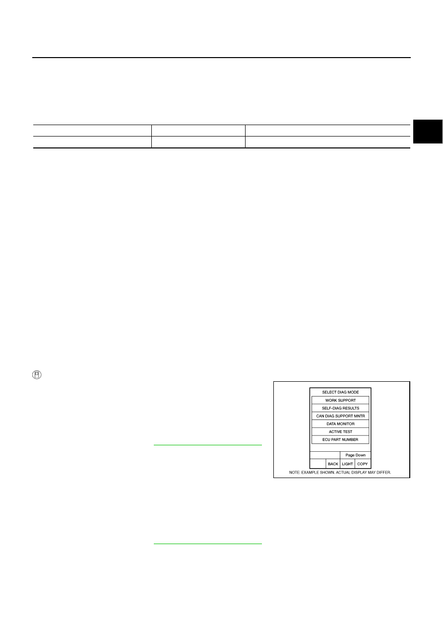
Select “SELECTION FROM MENU” in “DATA MONITOR” mode
for “A/T” with CONSULT-II and check monitor “VHCL/S SE-A/T”,
“ACCELE POSI”, “ENGINE SPEED” and “SLCT LVR POSI”.
6.
Start engine and maintain the following conditions for at least 5 consecutive seconds.
VHCL/S SE-A/T: 30 km/h (19 MPH) or more
ACCELE POSI: More than 1.0/8
SLCT LVR POSI: “D” position
Driving location: Driving the vehicle uphill (increased engine load) will help maintain the driving
conditions required for this test.
If the check result is NG, go to
AT-116, "Diagnostic Procedure"
.
If the check result is OK, go to following step.
7.
Maintain the following conditions for at least 5 consecutive seconds.
ENGINE SPEED: 3,500 rpm or more
ACCELE POSI: More than 1.0/8
Item name
Condition
Display value
VHCL/S SE-A/T
During driving
Approximately matches the speedometer reading.
BCIA0031E