Infiniti Q45 (FY33). Manual - part 99
 

  Index      Infiniti     Infiniti Q45 (FY33) - service repair manual 2001 year


Search            copyright infringement  


Content   ..  97  98  99  100   ..


Infiniti Q45 (FY33). Manual - part 99


SBR684D

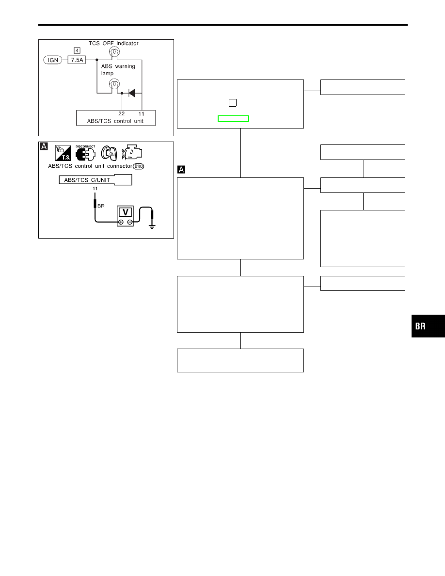
Diagnostic Procedure 24 (TCS OFF indicator
does not come on when ignition switch is
turned on.)

SBR392E

WARNING LAMP CIRCUIT CHECK

----------------------------------------------------------------------------------------------------------------------------------------------------------------------------------------------------------------------------------------------------------------------------------------------------------------

Check 7.5A fuse

4

for warning lamp. For

fuse layout, refer to POWER SUPPLY
ROUTING in EL section.

OK

E

NG

Replace fuse.

Replace bulb.

G

NG

1. Install 7.5A fuse.
2. Disconnect connector from ABS/TCS

control unit.

3. Check voltage between ABS/TCS con-

trol unit connector terminal

q

11

and

ground after turning ignition switch
“ON”.
Battery voltage should exist after
turning ignition switch “ON”.

OK

E

NG

Check warning lamp bulb.

OK

Repair harness and con-
nectors between fuse box
and ABS/TCS control unit
connector terminal

q

11

(including combination
meter).

1. Disconnect connectors from ABS/TCS

control unit. Check terminals for dam-
age or loose connection. Then recon-
nect connectors.

2. Carry out self-diagnosis again.

Does warning lamp activate again?

Yes

E

No

Inspection end

Check items the self-diagnosis detected
as faulty.

GI

MA

EM

LC

EC

FE

AT

PD

FA

RA

ST

RS

BT

HA

EL

IDX

TROUBLE DIAGNOSES FOR SYMPTOMS

H

H

H

H

BR-113

SBR393E

Diagnostic Procedure 25 (ABS warning lamp
does not come on when ignition switch is
turned on.)

SBR394E

SBR395E

SBR396E

WARNING LAMP CIRCUIT CHECK

----------------------------------------------------------------------------------------------------------------------------------------------------------------------------------------------------------------------------------------------------------------------------------------------------------------

Check 7.5A fuse

4

for warning lamp. For

fuse layout, refer to POWER SUPPLY
ROUTING in EL section.

OK

E

NG

Replace fuse.

Replace bulb.

G

NG

1. Install 7.5A fuse.
2. Disconnect connectors from ABS/TCS

control unit and actuator.

3. Check voltage between ABS/TCS con-

trol unit connector terminal

q

22

and

ground after turning ignition switch
“ON”.
Battery voltage should exist after
turning ignition switch “ON”.

OK

E

NG

Check warning lamp bulb.

OK

Repair harness and con-
nectors between fuse box
and ABS/TCS control unit
connector terminal

q

22

(including combination
meter).

1. Turn ignition switch “OFF”.

Disconnect ABS actuator 8-pin connec-
tor.

2. Check continuity between ABS/TCS

control unit connector terminal

q

22

and

ABS actuator 8-pin connector (body
side) terminal

q

11

.

Continuity should exist.

OK

E

NG

Repair harness and con-
nectors between ABS
warning lamp (combination
meter) and ABS actuator
8-pin connector (body side)
terminal

q

11

.

1. Disconnect ABS actuator 8-pin connec-

tor.

2. Check continuity between ABS actuator

harness 8-pin connector (body side)
terminal

q

21

and body ground.

Continuity should exist.

OK

E

NG

Repair harness and con-
nectors.

q

A

(Go to next page.)

TROUBLE DIAGNOSES FOR SYMPTOMS

H

H

H

H

H

BR-114

SBR397E

SBR376E

q

A

1. Disconnect ABS actuator 8-pin connec-

tor.

2. Check continuity between ABS actuator

8-pin connector (ABS actuator side)
terminals

q

11

@

and

q

21

!

.

Continuity should exist.

Note: Pay attention to tester polarity*.

OK

E

NG

Replace ABS actuator.

CONTROL UNIT POWER SUPPLY CIR-
CUIT.

----------------------------------------------------------------------------------------------------------------------------------------------------------------------------------------------------------------------------------------------------------------------------------------------------------------

Go to

in Diagnostic Procedure 26,

BR-116.

OK

E

NG

Repair harness and con-
nectors.

CHECK SOLENOID VALVE RELAY.

----------------------------------------------------------------------------------------------------------------------------------------------------------------------------------------------------------------------------------------------------------------------------------------------------------------

OK

E

NG

Replace ABS relay unit.

Go to Diagnostic Procedure 11, BR-96.

*: Specifications may vary depending on the type of tester.

Before performing this inspection, refer to the instruction manual of
the tester.

Relay type

Solenoid valve

relay

Condition

Continuity exist-

ence between

terminals

q

6

and

q

21

Battery voltage
not applied
between each
terminal

q

5

and

q

7

Yes

Battery voltage
applied
between each
terminal

q

5

and

q

7

No

Check resis-
tance between
each terminal

q

5

and

q

7

Approx. 100

Ω

GI

MA

EM

LC

EC

FE

AT

PD

FA

RA

ST

RS

BT

HA

EL

IDX

TROUBLE DIAGNOSES FOR SYMPTOMS

Diagnostic Procedure 25 (ABS warning lamp
does not come on when ignition switch is
turned on.) (Cont’d)

H

H

H

H

BR-115

SBR371E

Diagnostic Procedure 26 (ABS warning lamp
stays on when ignition switch is turned on.)

SBR398E

SBR399E

SBR400E

CONTROL UNIT POWER SUPPLY
CIRCUIT

----------------------------------------------------------------------------------------------------------------------------------------------------------------------------------------------------------------------------------------------------------------------------------------------------------------

Check 7.5A fuse

31

for control unit.

For fuse layout, refer to POWER SUPPLY
ROUTING in EL section.

OK

E

NG

q

B

(Skip page.)

1. Disconnect connector from ABS/TCS

control unit.

2. Check voltage between ABS/TCS con-

trol unit connector terminal

108

and

ground after turning ignition switch
“ON”.
Battery voltage should exist.

OK

E

NG

Check the following.

I

Harness connector

B103

I

Harness for open or
short between control
unit and fuse

If NG, repair harness or
connectors.

SOLENOID VALVE RELAY COIL
POWER SUPPLY CIRCUIT

----------------------------------------------------------------------------------------------------------------------------------------------------------------------------------------------------------------------------------------------------------------------------------------------------------------

1. Turn ignition switch “OFF”. Disconnect

ABS actuator 8-pin connector.

2. Check continuity between ABS/TCS

control unit connector terminals and
ABS actuator 8-pin connector (body
side) terminals.

Continuity should exist.

OK

E

NG

Check the following.

I

Harness connectors

B103

,

F7

I

Harness for open or short
between actuator terminal
(body side) and ABS/TCS
control unit

If NG, repair harness or
connectors.

CIRCUIT CHECK

----------------------------------------------------------------------------------------------------------------------------------------------------------------------------------------------------------------------------------------------------------------------------------------------------------------

1. Disconnect ABS actuator 8-pin connec-

tor.

2. Check continuity between ABS actuator

8-pin connector (ABS actuator side)
terminals

q

5

and

q

7

.

Continuity should exist.

OK

E

NG

Replace ABS actuator.

SOLENOID VALVE RELAY CHECK

----------------------------------------------------------------------------------------------------------------------------------------------------------------------------------------------------------------------------------------------------------------------------------------------------------------

Go to

in Diagnostic Procedure 25,

BR-115.

OK

E

NG

Replace ABS actuator.

q

A

(Go to next page.)

ABS/TCS control unit

ABS actuator

108

q

5

q

7

q

7

TROUBLE DIAGNOSES FOR SYMPTOMS

H

H

H

H

H

BR-116


Content   ..  97  98  99  100   ..