Infiniti Q45 (FY33). Manual - part 98


  Index      Infiniti     Infiniti Q45 (FY33) - service repair manual 2001 year


Search            copyright infringement  


Content   ..  96  97  98  99   ..


Infiniti Q45 (FY33). Manual - part 98


SBR043EA

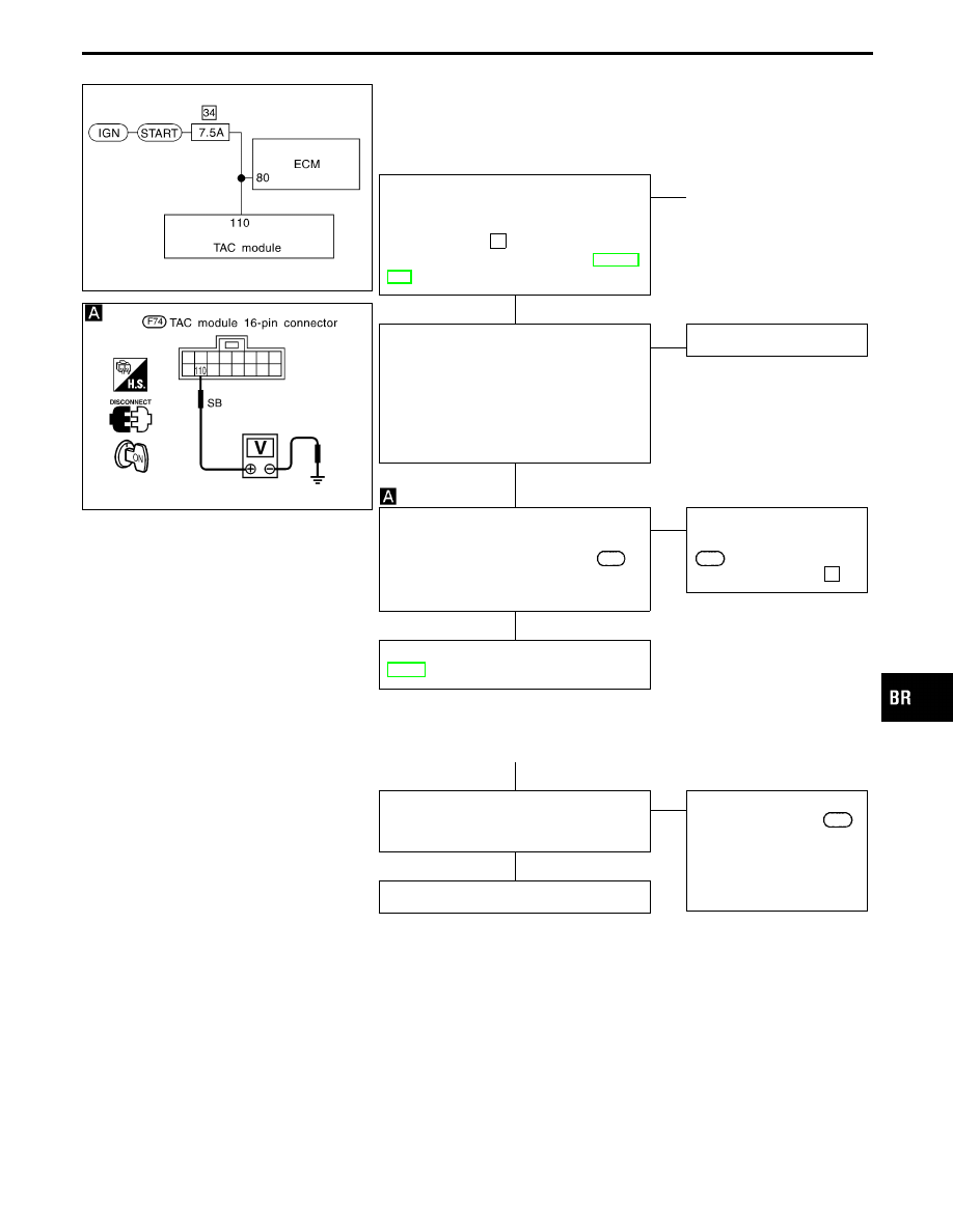
Diagnostic Procedure 21 (ENGINE START SIG:
Start signal circuit)

Code No. 31 of TAC module

SBR600CD

START SIGNAL POWER SUPPLY
CHECK

----------------------------------------------------------------------------------------------------------------------------------------------------------------------------------------------------------------------------------------------------------------------------------------------------------------

Check 7.5A fuse

34

. For fuse layout, refer

to POWER SUPPLY ROUTING in EL sec-
tion.

OK

E

NG

q

A

(See below.)

1. Disconnect connectors from TAC mod-

ule. Check terminals for damage or
loose connection. Then reconnect con-
nectors.

2. Carry out self-diagnosis again.

Do SLIP indicator and TCS OFF indi-
cator activate again?

Yes

E

No

Inspection end

I

Reconnect ECM connector.

I

Turn ignition switch ON.

I

Check voltage between terminal

110

for TAC module connector and ground.
Voltage: Approx. 12V

OK

E

NG

Repair harness and con-
nectors between terminal

110

for TAC module con-

nector and 7.5A fuse

34

.

Preliminary check (Basic inspection 3),
BR-48

q

A

Replace fuse.
Does the fuse blow out when ignition
switch is turned “START”?

No

E

Yes

Check the following.

I

Harness connector

F74

I

Harness for open or
short between TAC mod-
ule connector and fuse

If NG, repair harness or
connectors.

Inspection end

GI

MA

EM

LC

EC

FE

AT

PD

FA

RA

ST

RS

BT

HA

EL

IDX

TROUBLE DIAGNOSES FOR SELF-DIAGNOSTIC ITEMS

H

H

H

H

H

BR-109

SBR680DA

Diagnostic Procedure 22 (NEUTRAL POSI SW:
Park/Neutral position (PNP) switch circuit)

Code No. 33 of TAC module

SBR516CA

SBR183DA

PNP SWITCH POWER SUPPLY CHECK

----------------------------------------------------------------------------------------------------------------------------------------------------------------------------------------------------------------------------------------------------------------------------------------------------------------

Check 10A fuse

18

. For fuse layout, refer

to POWER SUPPLY ROUTING in EL sec-
tion.

OK

E

NG

q

A

(Go to next page.)

1. Disconnect connectors from TAC mod-

ule. Check terminals for damage or
loose connection. Then reconnect con-
nectors.

2. Carry out self-diagnosis again.

Do SLIP indicator and TCS OFF indi-
cator activate again?

Yes

E

No

Inspection end

Does TAC module display code No. 33
still when shifting selector lever to all posi-
tions with ignition switch ON?

Yes

E

No

Inspection end

I

Disconnect 20-pin connector from TAC
module.

I

Turn ignition switch ON.

I

Check continuity between terminal

q

6

and ground when shifting selector lever
to all positions.
Continuity should exist when shifting
to “P” and “N”.
Continuity should not exist when
shifting to other than “P” and “N”.

NG

E

OK

Inspection end

I

Turn ignition switch OFF.

I

Remove park/neutral position relay.

I

Check continuity between terminal

q

6

for TAC module connector and terminal

q

6

for park/neutral position relay con-

nector.
Continuity should exist.

OK

E

NG

Repair harness and con-
nectors.

Inspection end

TROUBLE DIAGNOSES FOR SELF-DIAGNOSTIC ITEMS

H

H

H

H

H

BR-110

SBR518CA

SBR184DA

SBR185DA

q

A

Check continuity between terminal

q

6

for

TAC module connector and ground.
Continuity should not exist.

OK

E

NG

Repair harness and con-
nectors.

Check continuity between terminal

q

7

for

park/neutral position relay connector and
ground.
Continuity should exist.

OK

E

NG

Repair harness and con-
nectors.

CHECK PARK/NEUTRAL POSITION
RELAY.
Refer to PARK/NEUTRAL POSITION
RELAY in Electrical Component
Inspection, BR-126.

OK

E

NG

Replace park/neutral posi-
tion relay.

I

Turn ignition switch ON.

I

Check voltage between terminal

q

1

for

park/neutral position relay connector
and ground when shifting selector lever
to “P” & “N”.
Battery voltage should exist.

NG

E

OK

Repair harness and con-
nectors between terminal

q

2

for park/neutral position

relay connector and
ground.

CHECK PNP SWITCH.
Refer to PNP SWITCH in Electrical Com-
ponent Inspection, BR-127.

OK

E

NG

Replace PNP switch.

Check continuity between terminals

q

7

and

q

9

for PNP switch connector and ter-

minal

q

1

for park/neutral position relay

connector.
Continuity should exist.

OK

E

NG

Repair harness and con-
nectors.

Repair harness and connectors between
terminal

q

3

for PNP switch connector and

fuse block.
or
Check 10A fuse

18

. For fuse layout, refer

to foldout page of Circuit Diagram.

GI

MA

EM

LC

EC

FE

AT

PD

FA

RA

ST

RS

BT

HA

EL

IDX

TROUBLE DIAGNOSES FOR SELF-DIAGNOSTIC ITEMS

Diagnostic Procedure 22 (NEUTRAL POSI SW:
Park/Neutral position (PNP) switch circuit)
(Cont’d)

H

H

H

H

H

H

H

BR-111

SBR648E

Diagnostic Procedure 23 (SLIP indicator does
not come on when ignition switch is turned
on.)

SBR390E

SBR649E

CONTROL UNIT POWER SUPPLY
CIRCUIT

----------------------------------------------------------------------------------------------------------------------------------------------------------------------------------------------------------------------------------------------------------------------------------------------------------------

Check 7.5A fuse

4

for control unit.

For fuse layout, refer to POWER SUPPLY
ROUTING in EL section.

OK

E

NG

Replace fuse.

Replace bulb.

G

NG

1. Disconnect connector from ABS/TCS

control unit.

2. Check voltage between ABS/TCS con-

trol unit connector terminal

q

10

and

ground after turning ignition switch
“ON”.
Battery voltage should exist.

OK

E

NG

Check warning lamp bulb.

OK

Check the following.

I

Harness connector

B103

I

Harness for open or
short between ABS/TCS
control unit and fuse

If NG, repair harness or
connectors.

CIRCUIT CHECK

----------------------------------------------------------------------------------------------------------------------------------------------------------------------------------------------------------------------------------------------------------------------------------------------------------------

1. Disconnect ABS/TCS control unit con-

nector.

2. Check continuity between ABS/TCS

control unit connector terminal

q

31

and

terminal

q

9

of data link connector.

Continuity should exist.

OK

E

NG

Check the following.

I

Harness connectors

B103

,

M5

I

Harness for open or short
between data link con-
nector terminal and ABS/
TCS control unit

If NG, repair harness or
connectors.

1. Disconnect connectors from ABS/TCS

control unit. Check terminals for dam-
age or loose connection. Then recon-
nect connectors.

2. Carry out self-diagnosis again.

Does warning lamp activate again?

Yes

E

No

Inspection end

Check items the self-diagnosis detected
as faulty.

TROUBLE DIAGNOSES FOR SYMPTOMS

H

H

H

H

H

BR-112


Content   ..  96  97  98  99   ..