Infiniti M45 (Y34). Manual - part 785


  Index      Infiniti     Infiniti M45 (Y34) - service repair manual 2004 year


Search            copyright infringement  


Content   ..  783  784  785  786   ..


Infiniti M45 (Y34). Manual - part 785


TROUBLE DIAGNOSIS

SRS-27

C

D

E

F

G

I

J

K

L

M

A

B

SRS

DIAGNOSTIC PROCEDURE 4 (CONTINUED FROM DIAGNOSTIC PROCEDURE 2)

Inspecting SRS malfunctioning record

1. 

CONSIDER POSSIBILITY OF NOT ERASING SELF-DIAGNOSTIC RESULTS AFTER REPAIRING

Is it the first time for maintenance of SRS?

YES or NO

YES

>> Go to 

SRS-21, "DIAGNOSTIC PROCEDURE 2"

 .

NO

>> Self-diagnostic results “SELF-DIAG [PAST]” (previously stored in the memory) might not be

erased after repair. Go to 

SRS-25, "DIAGNOSTIC PROCEDURE 3"

 .

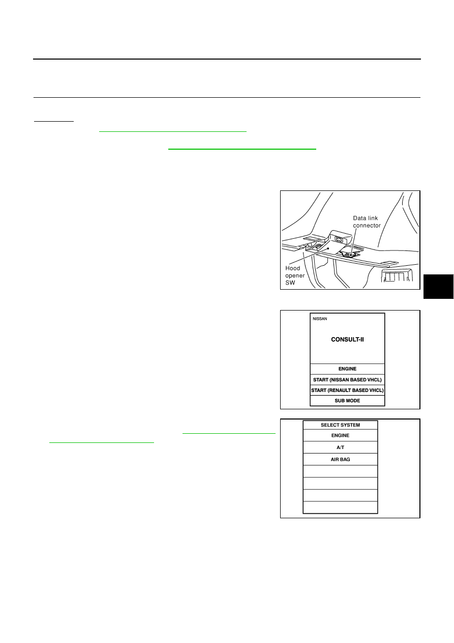
DIAGNOSTIC PROCEDURE 5

Inspecting SRS intermittent malfunction by using CONSULT-II — Diagnosis mode

1.

Turn ignition switch OFF.

2.

Connect CONSULT-II and CONSULT-II CONVERTER to data
link connector.

3.

Turn ignition switch ON.

4.

Touch “START (NISSAN BASED VHCL)”.

5.

Touch “AIR BAG”.
If “AIR BAG” is not indicated, go to 

GI-38, "CONSULT-II Data

Link Connector (DLC) Circuit"

 .

SHIA0179E

PHIA0157E

SRS771

SRS-28

TROUBLE DIAGNOSIS

6.

Touch “SELF-DIAG [PAST]”.

7.

If diagnostic codes are displayed on “SELF-DIAG [PAST]”, go to
step 10.

If no malfunction is detected on “SELF-DIAG [PAST]”, touch
“BACK” and go back to “SELECT DIAG MODE”.

8.

Touch “TROUBLE DIAG RECORD”.

NOTE:
With “TROUBLE DIAG RECORD”, diagnosis results previously
erased by a reset operation can be displayed.

9.

Diagnostic code is displayed on “TROUBLE DIAG RECORD”.

10. Touch “PRINT”.

11. Compare diagnostic codes to 

SRS-29, "CONSULT-II Diagnostic

Code Chart (“SELF-DIAG [PAST]” or “TROUBLE DIAG
RECORD”)"

 .

12. Touch “BACK” key of CONSULT-II until “SELECT SYSTEM”

appears.

13. Turn ignition switch OFF, then turn off and disconnect CON-

SULT-II, and both battery cables.

SRS697

SRS700

SRS702

SRS697

SHIA0182E

TROUBLE DIAGNOSIS

SRS-29

C

D

E

F

G

I

J

K

L

M

A

B

SRS

14. Repair the system as outlined by the “Repair order” in “Intermittent Malfunction Diagnostic Code Chart”,

that corresponds to the self-diagnostic results. For replacement procedure of component parts, refer to
the Removal and Installation procedure for the appropriate component.

15. Go to 

SRS-25, "DIAGNOSTIC PROCEDURE 3"

 , for final inspection.

CONSULT-II Diagnostic Code Chart (“SELF-DIAG [PAST]” or “TROUBLE DIAG RECORD”)

Diagnostic item

Explanation

Repair order

“Recheck SRS at each replacement”

NO DTC IS 
DETECTED.

When malfunction is 
indicated by the “AIR 
BAG” warning lamp in 
User mode.

Low battery voltage (Less than 9V)

Go to 

SRS-25, "DIAGNOSTIC PRO-

CEDURE 3"

 . 

No malfunction is detected.

Go to 

SRS-25, "DIAGNOSTIC PRO-

CEDURE 3"

 . 

DRIVER AIRBAG 
MODULE
[OPEN]

Driver air bag module circuit is open (including the spiral cable).

1. Visually check the wiring harness 

connection.

2. Replace the harness if it has visible 

damage.

3. If the harness check result is OK, 

replace driver air bag module, diag-
nosis sensor unit and spiral cable. 
(Before disposal, it must be 
deployed.)

DRIVER AIRBAG 
MODULE
[VB-SHORT]

Driver air bag module circuit is shorted to a power supply circuit 
(including the spiral cable).

DRIVER AIRBAG 
MODULE
[GND-SHORT]

Driver air bag module circuit is shorted to ground (including the 
spiral cable).

DRIVER AIRBAG 
MODULE
[SHORT]

Driver air bag module circuit is shorted between lines.

ASSIST A/B MODULE
[OPEN]

Front passenger air bag module circuit is open.

1. Visually check the wiring harness 

connection.

2. Replace the harness if it has visible 

damage.

3. If the harness check result is OK, 

replace the diagnosis sensor unit 
and front passenger air bag module. 
(Before disposal, it must be 
deployed.)

ASSIST A/B MODULE
[VB-SHORT]

Front passenger air bag module circuit is shorted to a power 
supply circuit.

ASSIST A/B MODULE
[GND-SHORT]

Front passenger air bag module circuit is shorted to ground.

ASSIST A/B MODULE
[SHORT]

Front passenger air bag module circuit is shorted between lines.

CRASH ZONE SEN
[UNIT FAIL]
CRASH ZONE SEN
[COMM FAIL]
CRASH ZONE SEN
[UNMATCH]

Crash zone sensor

1. Visually check the wiring harness 

connection.

2. Replace the harness if it has visible 

damage.

3. If the harness check result is OK, 

replace crash zone sensor and diag-
nosis sensor unit.

SIDE MODULE LH
[OPEN]

Front LH side air bag module circuit is open.

1. Visually check the wiring harness 

connection.

2. Replace the harness if it has visible 

damage.

3. If the harness check result is OK, 

replace the diagnosis sensor unit 
and LH side air bag module. (Before 
disposal, it must be deployed.)

SIDE MODULE LH
[VB-SHORT]

Front LH side air bag module circuit is shorted to a power sup-
ply circuit.

SIDE MODULE LH
[GND-SHORT]

Front LH side air bag module circuit is shorted to ground.

SIDE MODULE LH
[SHORT]

Front LH side air bag module circuit is shorted between lines.

SRS-30

TROUBLE DIAGNOSIS

SIDE MODULE RH
[OPEN]

Front RH side air bag module circuit is open.

1. Visually check the wiring harness 

connection.

2. Replace the harness if it has visible 

damage.

3. If the harness check result is OK, 

replace the diagnosis sensor unit 
and RH side air bag module.
(Before disposal, it must be 
deployed.)

SIDE MODULE RH
[VB-SHORT]

Front RH side air bag module circuit is shorted to a power sup-
ply circuit.

SIDE MODULE RH
[GND-SHORT]

Front RH side air bag module circuit is shorted to ground.

SIDE MODULE RH
[SHORT]

Front RH side air bag module circuit is short between lines.

SATELLITE SENS LH
[UNIT FAIL]
SATELLITE SENS LH
[COMM FAIL]
SATELLITE SENS LH
[UNMATCH]

LH side air bag (Satellite) sensor

1. Visually check the wiring harness 

connection.

2. Replace the harness if it has visible 

damage.

3. If the harness check result is OK, 

replace the diagnosis sensor unit 
and LH side air bag (Satellite) sen-
sor.

SATELLITE SENS RH
[UNIT FAIL]
SATELLITE SENS RH
[COMM FAIL]
SATELLITE SENS RH
[UNMATCH]

RH side air bag (Satellite) sensor

1. Visually check the wiring harness 

connection.

2. Replace the harness if it has visible 

damage.

3. If the harness check result is OK, 

replace the diagnosis sensor unit 
and RH side air bag (Satellite) sen-
sor.

PRE-TEN FRONT LH
[OPEN]

Front LH pre-tensioner circuit is open. 

1. Visually check the wiring harness 

connections.

2. Replace the harness if it has visible 

damage.

3. If the harness check result is OK, 

replace the diagnosis sensor unit 
and front LH seat belt.
(Before disposal, it must be deacti-
vated.)

PRE-TEN FRONT LH
[VB-SHORT]

Front LH pre-tensioner circuit is shorted to a power supply cir-
cuit.

PRE-TEN FRONT LH
[GND-SHORT]

Front LH pre-tensioner circuit is shorted to ground.

PRE-TEN FRONT LH
[SHORT]

Front LH pre-tensioner circuit is shorted between lines

PRE-TEN FRONT RH
[OPEN]

Front RH pre-tensioner circuit is open.

1. Visually check the wiring harness 

connections.

2. Replace the harness if it has visible 

damage.

3. If the harness check result is OK, 

replace the diagnosis sensor unit 
and front RH seat belt.
(Before disposal, it must be deacti-
vated.)

PRE-TEN FRONT RH
[VB-SHORT]

Front RH pre-tensioner circuit is shorted to a power supply cir-
cuit.

PRE-TEN FRONT RH
[GND-SHORT]

Front RH pre-tensioner circuit is shorted to ground.

PRE-TEN FRONT RH
[SHORT]

Front LH pre-tensioner circuit is shorted between lines.

CURTAIN MODULE LH
[OPEN]

LH side curtain air bag module circuit is open.

1. Visually check the wiring harness 

connection.

2. Replace the harness if it has visible 

damage.

3. If the harness check result is OK, 

replace the diagnosis sensor unit 
and LH side curtain air bag module.
(Before disposal, it must be 
deployed.)

CURTAIN MODULE LH
[VB-SHORT]

LH side curtain air bag module circuit is shorted to a power sup-
ply circuits.

CURTAIN MODULE LH
[GND-SHORT]

LH side curtain air bag module circuit is shorted to ground.

CURTAINMODULE LH
[SHORT]

LH side curtain air bag module circuit is shorted between lines.

Diagnostic item

Explanation

Repair order

“Recheck SRS at each replacement”


Content   ..  783  784  785  786   ..