Infiniti M45 (Y34). Manual - part 763
AUTOMATIC DRIVE POSITIONER
SE-73
C
D
E
F
G
H
J
K
L
M
A
B
SE
6.
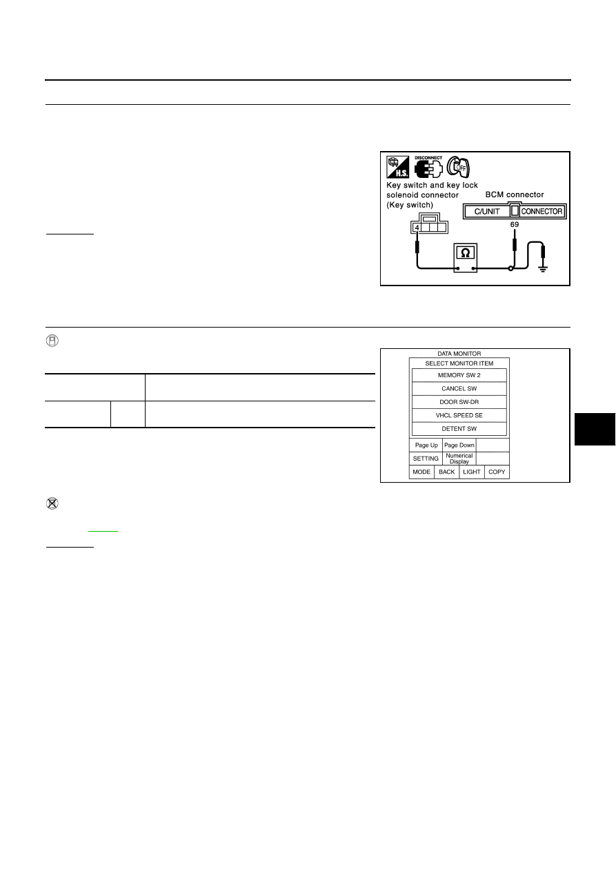
CHECK HARNESS CONTINUITY
1.
Disconnect key switch and key lock solenoid connector and BCM connector.
2.
Check continuity between key switch and key lock solenoid connector M64 terminal 4 (PU/W) and BCM
connector M4 terminal 69 (PU/W).
3.
Check continuity between key switch and key lock solenoid con-
nector M64 terminal 4 (PU/W) and body ground.
OK or NG
OK
>> Check the harness and connector.
NG
>> Repair or replace harness between key switch and key
lock solenoid and BCM.
Front Door Switch (Driver Side) Circuit Inspection
AIS001KA
1.
CHECK FUNCTION
With CONSULT-II
With “DOOR SW DR” on the DATA MONITOR, check ON/OFF oper-
ation when the driver door is open and closed.
Without CONSULT-II
Carry out “SWITCH MONITOR” in the self-diagnosis function, and open and close the driver door to check.
Refer to
.
OK or NG
OK
>> System is OK.
NG
>> GO TO 2.
4 (PU/W) – 69 (PU/W)
: Continuity should exist.
4 (PU/W) – Ground
: Continuity should not exist.
PIIA3287E
Monitor item [OPERA-
TION or UNIT]
Contents
DOOR SW
DR
ON/
OFF
Door open (ON)/door closed (OFF) status judged from
the driver door switch is displayed.
PIIA0291E