Infiniti M45 (Y34). Manual - part 762
AUTOMATIC DRIVE POSITIONER
SE-69
C
D
E
F
G
H
J
K
L
M
A
B
SE
4.
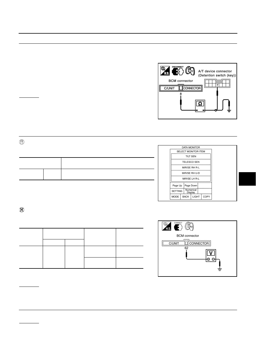
CHECK DETENTION SWITCH SIGNAL HARNESS
1.
Disconnect BCM connector.
2.
Check continuity between BCM connector M4 terminal 8 (G/OR) and A/T device (detention switch) con-
nector M97 terminal 7 (G/OR).
3.
Check continuity harness between BCM connector M4 terminal
8 (G/OR) and body ground.
OK or NG
OK
>> Replace BCM.
NG
>> Repair or replace harness between BCM and A/T device
(detention switch).
Telescopic Sensor Circuit Inspection
AIS001K7
1.
CHECK FUNCTION
With CONSULT-II
Operate the telescopic switch with “TELESCO SEN” on the DATA
MONITOR to check that the voltage changes.
Without CONSULT-II
1.
Turn ignition switch OFF.
2.
Check voltage between BCM connector and body ground.
OK or NG
OK
>> System is OK.
NG
>> GO TO 2.
2.
CHECK STEERING WHEEL TILT MECHANISM
Check the operation malfunction caused by steering wheel tilt mechanism deformation or parts are loose.
OK or NG
OK
>> GO TO 3.
NG
>> Repair the malfunctioning parts.
8 (G/OR) – 7(G/OR)
: Continuity should exist.
8 (G/OR) – Ground
: Continuity should not exist.
PIIA3283E
Monitor item [OPERA-
TION or UNIT]
Contents
TELESCO
SEN
"V"
The telescoping position (voltage) judged from the tele-
scoping sensor signal is displayed.
PIIA0295E
Connector
Terminals
(Wire color)
Condition
Voltage (V)
(Approx)
(+)
(–)
M4
62 (P/B)
Ground
Telescopic
top position
2
Telescopic
bottom position
4
PIIA0296E