Infiniti M45 (Y34). Manual - part 679


  Index      Infiniti     Infiniti M45 (Y34) - service repair manual 2004 year


Search            copyright infringement  


Content   ..  677  678  679  680   ..


Infiniti M45 (Y34). Manual - part 679


CHASSIS AND BODY MAINTENANCE

MA-19

C

D

E

F

G

H

I

J

K

M

A

B

MA

CHASSIS AND BODY MAINTENANCE

PFP:00100

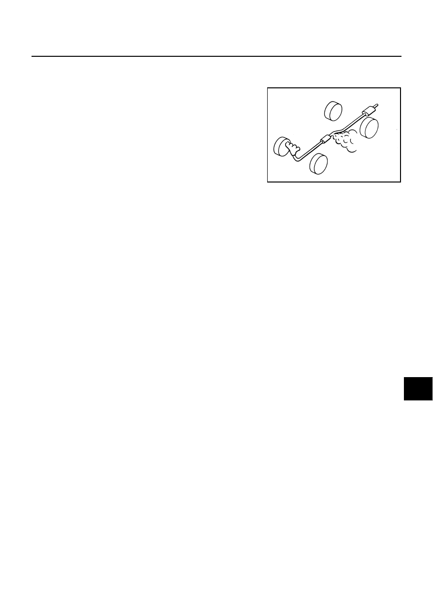
Checking Exhaust System

ALS00061

Check exhaust pipes, muffler and mounting for improper attachment,
leaks, cracks, damage, chafing or deterioration.

If anything is found, repair or replace damaged parts.

Checking A/T Fluid

ALS0005G

1.

Warm up engine.

2.

Check for fluid leakage.

3.

Loosen the level gauge bolt.

4.

Before driving, fluid level can be checked at fluid temperatures of 30 to 50

°

C (86 to 122

°

F) using “COLD”

range on A/T fluid level gauge as follows.

a.

Park vehicle on level surface and set parking brake.

b.

Start engine and move selector lever through each gear position. Leave selector lever in “P” position.

c.

Check fluid level with engine idling.

d.

Remove A/T fluid level gauge and wipe clean with lint-free paper.

CAUTION:

When wiping away the A/T fluid level gauge, always use lint-free paper, not a cloth one.

e.

Re-insert A/T fluid level gauge into charging pipe as far as it will go.

CAUTION:

To check fluid level, insert the A/T fluid level gauge until the cap contacts the end of the A/T fluid
charging pipe, with the A/T fluid level gauge reversed from the normal attachment conditions.

f.

Remove A/T fluid level gauge and note reading. If reading is at low side of range, add fluid to the charging
pipe.

CAUTION:

Do not overfill.

5.

Drive vehicle for approximately 5 minutes in urban areas.

6.

Make the fluid temperature approximately 65

°

C (149

°

F).

SMA211A

MA-20

CHASSIS AND BODY MAINTENANCE

NOTE:
Fluid level will be greatly affected by temperature as shown in the figure. Therefore, be certain to
perform operation while checking data with CONSULT-II.

a.

Connect CONSULT-II to data link connector.

b.

Select “MAIN SIGNALS” in “DATA MONITOR” mode for “A/T” with CONSULT-II.

c.

Read out the value of “ATF TEMP 1”.

7.

Re-check fluid level at fluid temperatures of approximately 65

°

C (149

°

F) using “HOT” range on A/T fluid

level gauge.

CAUTION:

When wiping away the fluid level gauge, always use lint-free paper, not a cloth one.

To check fluid level, insert the A/T fluid level gauge until
the cap contacts the end of the charging pipe, with the
gauge reversed from the normal attachment conditions
as shown in the figure.

8.

Check fluid condition.

If fluid is very dark or smells burned, refer to check operation
of A/T. Flush cooling system after repair of A/T.

If A/T fluid contains frictional material (clutches, bands, etc.),
replace radiator and flush cooler line using cleaning solvent
and compressed air after repair of A/T. Refer to 

CO-12,

"RADIATOR"

  and 

AT-16, "A/T Fluid Cooler Cleaning"

 .

9.

Install the removed A/T fluid level gauge in the fluid charging pipe.

Changing A/T Fluid

ALS0005H

1.

Warm up A/T fluid.

2.

Stop engine.

3.

Loosen the level gauge bolt.

4.

Drain A/T fluid from drain plug and refill with new A/T fluid. Always refill same volume with drained fluid.

To replace the A/T fluid, pour in new fluid at the charging pipe with the engine idling and at the same
time drain the old fluid from the radiator cooler hose return side.

When the color of the fluid coming out is about the same as the color of the new fluid, the replacement
is complete. The amount of new transmission fluid to use should be 30 to 50% increase of the stipu-
lated amount.

Level gauge bolt:

: 5.1 N·m (0.52 kg-m, 45 in-lb)

SLIA0019E

SCIA1684E

CHASSIS AND BODY MAINTENANCE

MA-21

C

D

E

F

G

H

I

J

K

M

A

B

MA

CAUTION:

Use only Genuine Nissan Matic J ATF. Do not mix with other fluid.

Using automatic transmission fluid other than Genuine Nissan Matic J ATF will cause deteriora-
tion in driveability and automatic transmission durability, and may damage the automatic trans-
mission, which is not covered by the warranty.

When filling A/T fluid, take care not to scatter heat generating parts such as exhaust.

Do not reuse drain plug gasket.

5.

Run engine at idle speed for 5 minutes.

6.

Check fluid level and condition. Refer to 

MA-19, "Checking A/T Fluid"

 . If fluid is still dirty, repeat step 2

through 5.

7.

Install the removed A/T fluid level gauge into fluid charging pipe.

8.

Tighten the level gauge bolt.

Checking Differential Gear Oil

ALS0005J

1.

Check for oil leakage.

A/T fluid: Genuine Nissan Matic J ATF

Fluid capacity: 10.3  (10-7/8 US pt, 9-1/8 lmp pt)

Drain plug:

: 34 N·m (3.5 kg-m, 25 ft-lb)

Level gauge bolt:

: 5.1 N·m (0.52 kg-m, 45 in-lb)

SMA012C

MA-22

CHASSIS AND BODY MAINTENANCE

Changing Differential Gear Oil

ALS0005K

1.

Drain oil from drain plug and refill with new gear oil.

2.

Check oil level.

CAUTION:

Gaskets are not reusable. Never reuse them.

Balancing Wheels (Bonding Weight Type)

ALS0005L

REMOVAL

1.

Remove inner and outer balance weights from the road wheel.

CAUTION:

Be careful not to scratch the road wheel during removal.

2.

Using releasing agent, remove double-faced adhesive tape from the road wheel.

CAUTION:

Be careful not to scratch the road wheel during removal.

After removing double-faced adhesive tape, wipe clean traces of releasing agent from the road
wheel.

WHEEL BALANCE ADJUSTMENT 

If a tire balance machine has adhesion balance weight mode settings and drive-in weight mode setting,
select and adjust a drive-in weight mode suitable for road wheels.

1.

Set road wheel on wheel balancer using the center hole as a guide. Start the tire balance machine.

2.

When inner and outer unbalance values are shown on the wheel balancer indicator, multiply outer unbal-
ance value by 5/3 to determine balance weight that should be used. Select the outer balance weight with
a value closest to the calculated value above and install it to the designated outer position of, or at the
designated angle in relation to the road wheel.

CAUTION:

Do not install the inner balance weight before installing the outer balance weight.

Before installing the balance weight, be sure to clean the
mating surface of the road wheel.

Indicated unbalance value 

×

 5/3 = balance weight to be installed

Calculation example:
23 g (0.81 oz) 

×

 5/3 = 38.33 g (1.35 oz) = 40 g (1.41 oz) balance

weight (closer to calculated balance weight value)
Note that balance weight value must be closer to the calculated
balance weight value.
Example:
37.4 = 35 g (1.23 oz)
37.5 = 40 g (1.41 oz)

Oil grade and Viscosity:

Refer to

MA-10, "RECOMMENDED FLUIDS 

AND LUBRICANTS"

 .

Capacity:

R200

1.4  (3 US pt, 2 - 1/2 lmp pt)

Drain plug:

: 34.5 N·m (3.5 kg-m, 25 ft-lb)

Filler plug:

: 34.5 N·m (3.5 kg-m, 25 ft-lb)

SDIA1151E

SMA054D


Content   ..  677  678  679  680   ..