Infiniti M45 (Y34). Manual - part 608
 

  Index      Infiniti     Infiniti M45 (Y34) - service repair manual 2004 year


Search            copyright infringement  


Content   ..  606  607  608  609   ..


Infiniti M45 (Y34). Manual - part 608


INSTRUMENT PANEL ASSEMBLY

IP-15

C

D

E

F

G

H

J

K

L

M

A

B

IP

2.

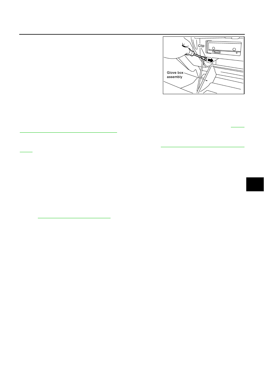
Remove both of the right and left two place clips of the strap.

3.

Remove glove box pins, and remove glove box.

(Q) Glove Box Cover

Remove screws with power tool and glove box striker, disconnect harness connectors, and remove glove box
cover. 

(R) CD Auto Changer

Remove bolts with power tool, disconnect harness connectors, and remove CD auto changer. Refer to

AV-30,

"Removal and Installation of CD Auto Changer"

 .

(S) Center Ventilator Grille

Pull back to your side and remove center ventilator grille. Refer to 

ATC-131, "Removal of Center Ventilator

Grille"

 .

(T) Console Box Assembly

1.

Remove screws with power tool. 

2.

Pull center console rearward of vehicle, and remove from instrument panel and rear cooler duct.

3.

Disconnect harness connectors, and remove console box assembly. 

(U) Front Defroster Grille (LH/RH)

Insert a remover into gaps between front defroster grille and instrument panel, lift front defroster grille up, and
remove front defroster grille.

(V) Front Pillar Garnish (LH/RH)

Pull front pillar garnish straight inside of vehicle, disconnect metal clips, and remove front pillar garnish. 
Refer to 

EI-34, "FRONT PILLAR GARNISH"

 .

(W) Instrument Panel Bracket

Remove ignition key lamp, remove screws, and remove instrument panel bracket. 

(X) Instrument Panel Reinforcement Bracket

Remove nuts, and remove instrument panel reinforcement bracket.

(Y) Instrument Panel And Pad

Remove bolts, nuts and screws securing instrument panel and pad, and remove instrument panel. 

INSTALLATION

Install in the reverse order of removal.

CAUTION:

To install, confirm locating pins on back of instrument panel are completely inserted into holes on
vehicle. 

Do not leave harness stuck when installing. 

PIIA2611E

IP-16

INSTRUMENT PANEL ASSEMBLY

Disassembly and Assembly

AIS001JB

CONSOLE BOX ASSEMBLY

Disassembly

1.

Remove console mask.

2.

Remove screws, and then remove console lid.

Assembly

Assemble in the reverse order of disassembly.

1.

Console lid

2.

Console body assembly

3.

Console mask

PIIB1583E

LAN-1

LAN SYSTEM

K  ELECTRICAL

CONTENTS

C

D

E

F

G

H

I

J

L

M

SECTION 

LAN

A

B

LAN

LAN SYSTEM

LAN

PRECAUTIONS .......................................................... 3

Precautions for Supplemental Restraint System 
(SRS) “AIR BAG” and “SEAT BELT PRE-TEN-
SIONER” .................................................................. 3

IVMS (LAN) ................................................................. 4

Overall Description ................................................... 4

OUTLINE ............................................................... 4
BCM (BODY CONTROL MODULE) ...................... 4
LCU (LOCAL CONTROL UNIT) ............................ 4
CONTROLLED SYSTEMS  ................................... 4

Component Parts and Harness Connector Location 

..... 5

Sleep/Wake-Up Control ............................................ 5

SLEEP CONTROL  ................................................ 5
WAKE-UP CONTROL  ........................................... 6

Fail-Safe System  ...................................................... 6
CONSULT–II Function  ............................................. 6

DIAGNOSTIC ITEMS DESCRIPTION  .................. 6
DIAGNOSTIC ITEMS APPLICATION  ................... 7

On Board Diagnosis  ................................................. 7

DIAGNOSIS ITEM ................................................. 7

Schematic ................................................................ 8

POWER SUPPLY, GROUND AND COMMUNI-
CATION CIRCUITS ............................................... 8

Wiring Diagram — COMM —  ................................... 9

POWER SUPPLY, GROUND AND COMMUNI-
CATION CIRCUITS ............................................... 9
WITH DOOR MIRROR MEMORY SYSTEM ....... 13

Schematic — BCM —  ............................................ 14
Schematic — LCU01 —  ......................................... 16

DRIVER'S DOOR CONTROL UNIT .................... 16

Schematic — LCU02 —  ......................................... 17

DRIVER'S SEAT CONTROL UNIT  ..................... 17

Schematic — LCU03 —  ......................................... 18

DRIVER'S SIDE DOOR MIRROR CONTROL 
UNIT (WITH DOOR MIRROR MEMORY SYS-
TEM) ................................................................... 18

Schematic — LCU04 —  ......................................... 19

PASSENGER SIDE DOOR MIRROR CONTROL 
UNIT (WITH DOOR MIRROR MEMORY SYS-

TEM) .................................................................... 19

CAN

PRECAUTIONS ........................................................ 20

Precautions for Supplemental Restraint System 
(SRS) “AIR BAG” and “SEAT BELT PRE-TEN-
SIONER” ................................................................. 20
Precautions For Trouble Diagnosis  ........................ 20

CAN SYSTEM  ..................................................... 20

Precautions For Harness Repair  ............................ 20

CAN SYSTEM  ..................................................... 20

CAN COMMUNICATION ........................................... 21

System Description ................................................. 21
CAN Communication Unit ....................................... 21

TYPE 1  ................................................................ 21
TYPE 2  ................................................................ 22

CAN SYSTEM (TYPE 1)  ........................................... 24

System Description ................................................. 24
Component Parts and Harness Connector Location 

... 24

Wiring Diagram — CAN —  ..................................... 25
Work Flow ............................................................... 27

CHECK SHEET  ................................................... 28
CHECK SHEET RESULTS (EXAMPLE)  ............. 29

Circuit Check Between VDC/TCS/ABS Control Unit 
and Data Link Connector ........................................ 32
ECM Circuit Check  ................................................. 33
VDC/TCS/ABS Control Unit Circuit Check  ............. 33
TCM Circuit Check  ................................................. 34
Steering Angle Sensor Circuit Check  ..................... 34
Combination Meter Circuit Check ........................... 35
CAN Communication Circuit Check ........................ 35
Component Inspection ............................................ 39

ECM/COMBINATION METER INTERNAL CIR-
CUIT INSPECTION  ............................................. 39

CAN SYSTEM (TYPE 2)  ........................................... 40

System Description ................................................. 40
Component Parts and Harness Connector Location 

... 40

Wiring Diagram — CAN —  ..................................... 41
Work Flow ............................................................... 43


Content   ..  606  607  608  609   ..