Infiniti M45 (Y34). Manual - part 595


  Index      Infiniti     Infiniti M45 (Y34) - service repair manual 2004 year


Search            copyright infringement  


Content   ..  593  594  595  596   ..


Infiniti M45 (Y34). Manual - part 595


REVERSE INTERLOCK DOOR MIRROR SYSTEM

GW-91

C

D

E

F

G

H

J

K

L

M

A

B

GW

4. 

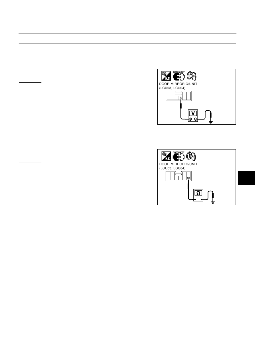
CHECK POWER SUPPLY CIRCUIT (DOOR MIRROR CONTROL UNIT)

1.

Turn ignition switch OFF.

2.

Disconnect door mirror control unit connector.

3.

Check voltage between door mirror control unit connector D5 (driver side), D35 (passenger side) terminal
8 and ground.

OK or NG?

OK

>> GO TO 5.

NG

>> Repair or replace harness.

5. 

CHECK GROUND CIRCUIT (DOOR MIRROR CONTROL UNIT)

Check continuity between door mirror control unit connector D5 (driver side), D35 (passenger side) terminal
10 and ground.

OK or NG?

OK

>> Preliminary check is OK.

NG

>> Repair or replace harness.

8 (L) – Ground

: Battery voltage

PIIA0171E

10 (B) – Ground

: Continuity should exist.

PIIA0172E

GW-92

REVERSE INTERLOCK DOOR MIRROR SYSTEM

CONSULT–II Function

AIS001HD

CONSULT–II executes the following functions by combining data received and command transmitted via the
communication line from BCM. IVMS communication inspection, work support (only function setting of seats
and steering wheel), self-diagnosis, data monitor, and active test display.

*: Only for function setting of seat and steering wheel

CONSULT-II BASIC OPERATION PROCEDURE

1.

Turn ignition switch OFF.

2.

Connect “CONSULT-II” and ”CONSULT-II CONVERTER” to the
data link connector.

3.

Turn ignition switch ON.

4.

Touch “START (NISSAN BASED VHCL)”.

5.

Touch "IVMS" on the "SELECT SYSTEM" screen.
If “IVMS” is not indicated, go to 

GI-39, "INSPECTION PROCE-

DURE"

 .

IVMS diagnosis 

position

Inspection item and diagno-

sis mode

Description

IVMS–
COMM CHECK

IVMS–COMM DIAGNOSIS

Diagnose a communication malfunction, inactive communication, and sleep 
malfunction in the communication line between BCM and each LCU.

WAKE–UP DIAGNOSIS

Diagnose the wake-up signals output from each LCU.

AUTO DRIVE
POSITIONER

WORK SUPPORT*

Changes the setting for each function. Refer to 

SE-36, "SETTING CHANGE 

FUNCTION"

 .

SELF–DIAG RESULTS

Carries out the self-diagnosis.

DATA MONITOR

Displays the input data of BCM and each LCU on real-time basis.

ACTIVE TEST

 Sends a drive signal to a load to check the operation.

BCM PART NUMBER

Displays BCM part No.

PBIB0196E

MBIB0233E

PIIA0183E

REVERSE INTERLOCK DOOR MIRROR SYSTEM

GW-93

C

D

E

F

G

H

J

K

L

M

A

B

GW

6.

Check the model specification, touch either “WITH SUNROOF”
or “WITHOUT SUNROOF” on the “SELECT SYS COND”
screen.

7.

Touch “OK”. If the selection is wrong, touch “CANCEL”.

8.

Select the desired part to be diagnosed on the
“SELECT TEST ITEM” screen.

IVMS COMMUNICATION INSPECTION

IVMS contains the IVMS communication diagnosis and wake–up diagnosis.

IVMS Communication Diagnosis

The IVMS communication diagnosis consists of the communication diagnosis, sleep diagnosis, and inactive
communication diagnosis between BCM and each local unit (LCU), and display the results on the CONSULT–
II screen. 

NOTE:
Sleep is a power saving function when a vehicle is stationary (all BCM related electrical equipment: OFF, and
the timer: OFF).
The function also stores the communication malfunction records and inactive communication records, and dis-
plays the data on the CONSULT–II screen (Malfunction record diagnosis)

*: malfunctioning item record

Operation Procedure

1.

Touch “IVMS–COMM CHECK” on “SELECT TEST ITEM”.

2.

Touch “IVMS–COMM DIAGNOSIS” on “SELECT DIAG ITEM” screen.

3.

Touch “START” on “IVMS–COMM DIAGNOSIS” screen to start the diagnosis.

4.

After the diagnosis is completed, the malfunctioning system is displayed.

5.

When the malfunctioning items are displayed, touch “PRINT” to record.

6.

Touch “ERASE”.

7.

Carry out the communication inspection again to check that any malfunctioning item is displayed.

8.

Check the displayed items. 

Wake – Up Diagnosis

The wake-up diagnosis is carried out when BCM detects the wake-up signal from each local unit (LCU). When
the switch shown on the screen is operated as instructed, each local control unit (LCU) outputs the wake-up
signal. If BCM cannot detect a wake-up signal, it is judged malfunctioning. The malfunctioning local control
unit (LCU) is displayed on the screen.

PIIA0184E

Malfunction description

CONSULT–II dis-

play item

Description

Communication malfunction

COMM DATA

Communicating with each LCU is judged sound when the communication is 
normally completed and the transmitted data and received data are identically 
the same. In other cases, it is judged malfunctioning. If the communication is 
inactive, no diagnosis result is displayed.

Inactive communication

NO RESPONSE

Communicating with each LCU is judged sound when at least one time com-
munication is normally completed within three trials. In other cases, it is 
judged malfunctioning.

Sleep malfunction

SLEEP

Check that each LCU enters sleep mode.

Communication malfunction *

PAST COMM
DATA

The records when communication signal malfunctions were continuously 
detected while the communication was normal are displayed. Or the records 
when a malfunction is detected during the past sleep mode are displayed.

Inactive communication*

PAST NO
RESPONSE

The records when inactive communications were continuously detected while 
the communication was normal are displayed.

GW-94

REVERSE INTERLOCK DOOR MIRROR SYSTEM

Operation Procedure

1.

Touch “IVMS–COMM CHECK” on “SELECT TEST ITEM” screen.

2.

Touch “WAKE–UP DIAGNOSIS” on “SELECT DIAG ITEM” screen.

3.

Touch “START” on “WAKE–UP DIAGNOSIS” screen to start the diagnosis.

4.

Touch “NEXT” to select the local control unit (LCU) to be diagnosed.

5.

Check that any malfunction is displayed. If necessary, touch “PRINT” to record.

6.

Carry out the inspection to the malfunctioning item.

Trouble Diagnosis Chart

NOTE:

For a specific local control unit (LCU), either "PAST COMM DATA" or "PAST NO RESPONSE" may be displayed instead of the
above results.The data record,  causes this, so erase the records.
(The display only shows the incident records, they are not malfunctions caused during the diagnosis. One possible cause is that an
intermittent incident occurred.)

Follow the steps below to erase the memory. 
Carry out either disconnect BCM battery power supply or erase memory with CONSULT-II.

With the battery connected, if the local control unit (LCU) connector is disconnected and left for approximately 1 minute, the BCM
stores "NO RESPONSE" record.

Malfunctioning 

item

Display unit

CONSULT–II IVMS communication 

diagnosis content

Self-diagnosis trou-

ble code No.

Malfunctioning system and 

reference

COMM DATA

One LCU is dis-
played.

POWER WINDOW  C/U–DR 
"COMM DATA"

24

Replace the displayed 
LCU.

DOOR MIRROR  C/U–RH 
"COMM DATA"

27

DOOR MIRROR  C/U–LH 
"COMM DATA"

37

POWER SEAT  C/U–DR
"COMM DATA"

47

Multiple LCUs 
are displayed

BCM
"COMM FAIL1" ,"COMM FAIL2"

Displays in order of 
24

27

37

47

and cycles from 24.

Communication system A: 
Refer to 

GW-95

 .

NO
RESPONSE

One LCU is dis-
played.

POWER WINDOW C/U–DR 
"NO RESPONSE"

25

Communication system B: 
Refer to 

GW-95

 .

DOOR MIRROR C/U–RH 
"NO RESPONSE"

28

DOOR MIRROR C/U–LH 
"NO RESPONSE"

38

POWER SEAT C/U–DR
"NO RESPONSE"

48

Multiple LCUs 
are displayed

BCM/HARNESS

Displays in order of 
25

28

38

48


and cycles from 25.

Communication system C: 
Refer to 

GW-95

 .

SLEEP malfunc-
tion

One LCU is dis-
played.

POWER WINDOW C/U–DR "SLEEP"

No self-diagnosis 
function

Replace the displayed 
LCU.

DOOR MIRROR C/U–RH 
"SLEEP"

DOOR MIRROR C/U–LH 
"SLEEP"

POWER SEAT C/U–DR 
"SLEEP"

Multiple LCUs 
are displayed

All the above control units are displayed.

No self-diagnosis 
function

Communication system A: 
Refer to 

GW-95

 .


Content   ..  593  594  595  596   ..