Infiniti M45 (Y34). Manual - part 494
INJECTOR CIRCUIT
EC-665
C
D
E
F
G
H
I
J
K
L
M
A
EC
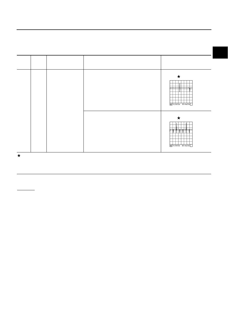
Specification data are reference values and are measured between each terminal and ground.
Pulse signal is measured by CONSULT-II.
CAUTION:
Do not use ECM ground terminals when measuring input/output voltage. Doing so may result in dam-
age to the ECM's transistor. Use a ground other than ECM terminals, such as the ground.
: Average voltage for pulse signal (Actual pulse signal can be confirmed by oscilloscope.)
Diagnostic Procedure
ABS002TT
1.
INSPECTION START
Turn ignition switch to START.
Is any cylinder ignited?
Yes or No
Yes
>> GO TO 2.
No
>> GO TO 3.
TER-
MINAL
NO.
WIRE
COLOR
ITEM
CONDITION
DATA (DC Voltage)
6
13
15
17
L
P
B/R
G
Injector No. 2
Injector No. 4
Injector No. 6
Injector No. 8
[Engine is running]
●
Warm-up condition
●
Idle speed
NOTE:
The pulse cycle changes depending on rpm at idle.
BATTERY VOLTAGE
(11 - 14V)
[Engine is running]
●
Warm-up condition
●
Engine speed: 2,000 rpm
BATTERY VOLTAGE
(11 - 14V)
PBIB0042E
PBIB0043E