Infiniti M45 (Y34). Manual - part 446
DTC P1143, P1163 HO2S1
EC-473
C
D
E
F
G
H
I
J
K
L
M
A
EC
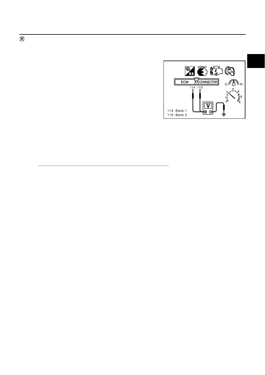
Without CONSULT-II
1.
Start engine and warm it up to normal operating temperature.
2.
Set voltmeter probes between ECM terminal 114 [HO2S1 (B1) signal] or 115 [HO2S1 (B2) signal] and
ground.
3.
Check the following with engine speed held at 2,000 rpm con-
stant under no load.
●
The voltage fluctuates between 0 to 0.3V and 0.6 to 1.0V
more than 5 times within 10 seconds.
●
The maximum voltage is over 0.6V at least 1 time.
●
The minimum voltage is below 0.3V at least 1 time.
●
The voltage never exceeds 1.0V.
1 time: 0 - 0.3V
→
0.6 - 1.0V
→
0 - 0.3V
2 times: 0 - 0.3V
→
0.6 - 1.0V
→
0 - 0.3V
→
0.6 - 1.0V
→
0 -
0.3V
CAUTION:
●
Discard any heated oxygen sensor which has been dropped from a height of more than 0.5 m (19.7
in) onto a hard surface such as a concrete floor; use a new one.
●
Before installing new oxygen sensor, clean exhaust system threads using Oxygen Sensor Thread
Cleaner tool J-43897-18 or J-43897-12 and approved anti-seize lubricant.
Removal and Installation
ABS002OG
HEATED OXYGEN SENSOR 1
Refer to
EM-22, "EXHAUST MANIFOLD AND THREE WAY CATALYST"
PBIB0063E