Index Infiniti Infiniti M45 (Y34) - service repair manual 2004 year
Search copyright infringement
Content .. 370 371 372 373 ..
Infiniti M45 (Y34). Manual - part 372
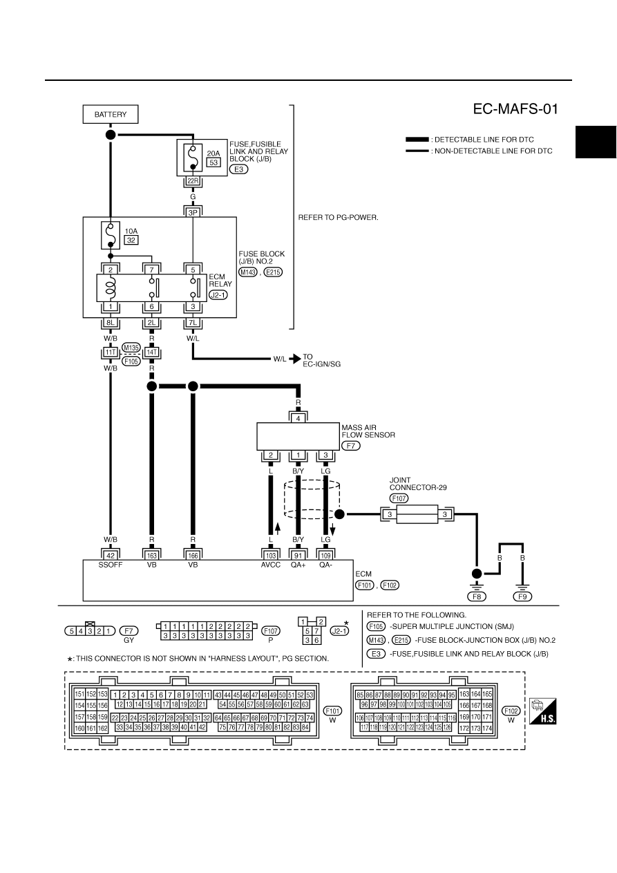
DTC P0101 MAF SENSOR
EC-177
C
D
E
F
G
H
I
J
K
L
M
A
EC
Wiring Diagram
ABS002F5
TBWA0271E