Infiniti M45 (Y34). Manual - part 318


  Index      Infiniti     Infiniti M45 (Y34) - service repair manual 2004 year


Search            copyright infringement  


Content   ..  316  317  318  319   ..


Infiniti M45 (Y34). Manual - part 318


VEHICLE INFORMATION AND INTEGRATED SWITCH SYSTEM /WITHOUT 

NAVIGATION SYSTEM

DI-117

C

D

E

F

G

H

I

J

L

M

A

B

DI

AUTO CLIMATE CONTROL

Refer to ATC Automatic Air Conditioner 

ATC-49, "Self-Diagnosis Function"

  for the details.

CONSULT-II Function

AKS00403

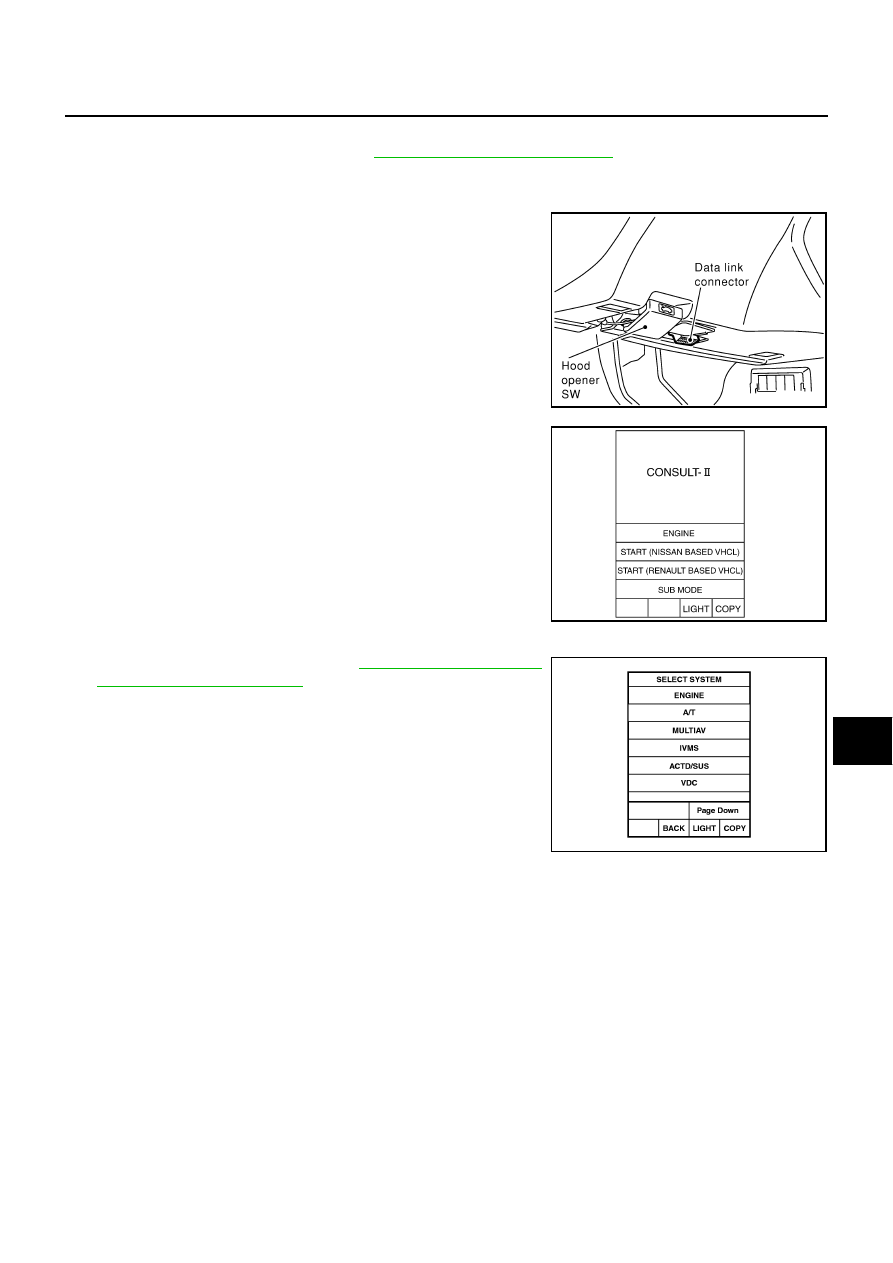
CONSULT-II BASIC OPERATION PROCEDURE

1.

With the ignition switch OFF, connect “CONSULT-II” and “CON-
SULT-ll CONVERTER” to the data link connector, and turn the
ignition switch ON.

2.

Touch “START(NISSAN BASED VHCL)”.

3.

Touch “MULTIAV” on “SELECT SYSTEM” screen.
If “MULTIAV” is not indicated, go to 

GI-38, "CONSULT-II Data

Link Connector (DLC) Circuit"

 .

4.

Select “VIRSION”, ”SELF-DIAG RESULTS” or “SIGNAL MONI-
TOR”.

SHIA0179E

SKIA3098E

PIIA0183E

DI-118

VEHICLE INFORMATION AND INTEGRATED SWITCH SYSTEM /WITHOUT 

NAVIGATION SYSTEM

SELF-DIAG RESULTS 

Checks for connection between each unit and analyzes each individual unit, then displays the results on
the screen.

Items Shown

NOTE:
When “IVCS ABNORMAL CONNECTION” and “REAR VIEW CAMERA ABNORMAL CONDITION” are
indicated, it does not malfunction.

DATA MONITOR

Displays status of the vehicle signal input to the AV control unit.
(Refer to 

DI-115, "Confirmation/Adjustment Mode"

  for operation

conditions for the connections to be indicated.)

For each signal, a comparison of actual operating status and the status recognized by the system can be
checked.

Items shown

Malfunctioning part/reference page

NO DTC IS DETECTED.
FURTHER TESTING MAY BEREQUIRED.

HEAD UNIT ABNORMAL

AV control unit malfunction

PANEL SW ABNORMAL CONNECTION

Refer to 

DI-114, "Quick Reference Table"

 .

AUDIO HEAD UNIT ABNORMAL CONNECTION

AIR COMP RECEIVER ABNORMAL CONNECTION

BOSE AMP ABNORMAL CONNECTION

BOSE AMP ABNORMAL

BOSE speaker amp. malfunction

VOICE UNIT ABNORMAL CONNECTION

Refer to 

DI-114, "Quick Reference Table"

 .

VOICE UNIT ABNORMAL

Voice activated control module malfunction.

REAR VIEW CAMERA ABNORMAL CONNECTION

See note.

PANEL SW ABNORMAL CONNECTION (MULTIFUNCTION SW)

Refer to 

DI-114, "Quick Reference Table"

 .

IVCS ABNORMAL CONNECTION

See note.

SKIA4181E

DATA MONITOR item

Display

Condition

Remarks

VHCL SPD SIG

ON

Vehicle speed >  0 km/h  (0 MPH)

Changes in indication may be delayed by 
approx. 1.5 seconds. This is normal.

OFF

Vehicle speed =  0 km/h  (0 MPH)

Ignition switch in ACC position

BRAKE

ON

This item cannot be monitored.
(No change of display)

MTR ILL DIM

ON

Lighting switch ON

OFF

Lighting switch OFF

IGN SW

ON

Ignition switch ON

OFF

Ignition switch ACC or OFF

NAVI ON SIG

OFF

This item cannot be monitored.
(No change of display)

VEHICLE INFORMATION AND INTEGRATED SWITCH SYSTEM /WITHOUT 

NAVIGATION SYSTEM

DI-119

C

D

E

F

G

H

I

J

L

M

A

B

DI

VERSION 

Displays version of each unit connected to the AV control unit.

Multifunction Switch Self-Diagnosis Function

AKS00404

It can check ON/OFF operation of each switch in the multifunction switch and diagnose the input signals to the
rear control switch (audio) and steering switch (audio).

STARTING THE SELF-DIAGNOSIS MODE

1.

Turn ignition switch from OFF to ACC.

2.

 Within 10 seconds press and hold the function switches “1” and
“6 ”simultaneously for 5 seconds.

Then the self-diagnosis operates.

EXITING THE SELF-DIAGNOSIS MODE

Turn ignition switch OFF, or press and hold the function switches “1” and “6” simultaneously for 5 seconds.
Then the self-diagnosis ends.

DIAGNOSIS FUNCTION 

It can illuminate all the indicators (LED) in the multifunction switch.

It can check for continuity of the switches by sounding the buzzer when the multifunction switch is
pressed.

It can check for continuity of harness between multifunction switch and rear control switch (audio), or
steering switch (audio).

SKIA3743E

Version display

Remarks

“PANEL SW”

Multifunction switch

“HEAD UNIT”

AV control unit

“REAR VIEW CAMERA”

“FRONT SEAT DISPLAY”

Display

“AUDIO HEAD UNIT”

“AIR COMP RECEIVER”

Low Tire Pressure Warning Control Unit

“BOSE AMP”

“IVCS”

“VOICE UNIT”

Voice Activated Control Module

SKIA0609E

DI-120

VEHICLE INFORMATION AND INTEGRATED SWITCH SYSTEM /WITHOUT 

NAVIGATION SYSTEM

Power Supply and Ground Circuit Inspection for AV Control Unit

AKS004OI

1. 

CHECK FUSE

Check AV control unit fuses are not blown.

OK or NG

OK

>> GO TO 2.

NG

>> If fuse is blown, be sure to eliminate cause of malfunction before installing new fuse. Refer to 

PG-

2, "POWER SUPPLY ROUTING"

 .

2. 

CHECK POWER SUPPLY CIRCUIT

1.

Disconnect AV control unit connector.  

2.

Check voltage between AV control unit and ground.

OK or NG

OK

>> GO TO 3.

NG

>> Check harness for open or short between AV control unit and fuse.

3. 

CHECK GROUND CIRCUIT

1.

Turn ignition switch OFF.

2.

Check continuity between AV control unit harness connector
M78 terminals 1 (B), 4 (B) and ground.

OK or NG

OK

>> Inspection end.

NG

>> Repair harness or connector.

Unit

Power source

Fuse No.

AV control unit

Battery power

52

Ignition switch ACC or ON

21

Terminals

Ignition switch position

(+)

(–)

OFF

ACC

ON

Connector

Terminal 

(Wire color)

M78

2 (SB)

Ground

Battery 
voltage

Battery 
voltage

Battery 
voltage

3 (SB)

Ground

Battery 
voltage

Battery 
voltage

Battery 
voltage

6 (L/B)

Ground

0V

Battery 
voltage

Battery 
voltage

SKIA3607E

Continuity should exist.

SKIA3608E


Content   ..  316  317  318  319   ..