Infiniti M45 (Y34). Manual - part 159


  Index      Infiniti     Infiniti M45 (Y34) - service repair manual 2004 year


Search            copyright infringement  


Content   ..  157  158  159  160   ..


Infiniti M45 (Y34). Manual - part 159


BLOWER MOTOR

ATC-121

C

D

E

F

G

H

I

K

L

M

A

B

ATC

BLOWER MOTOR

PFP:27226

Removal and Installation

AJS000QP

REMOVAL

1.

Remove the glove box, glove box cover and instrument lower cover. Refer to 

IP-11, "Removal and Instal-

lation"

 .

2.

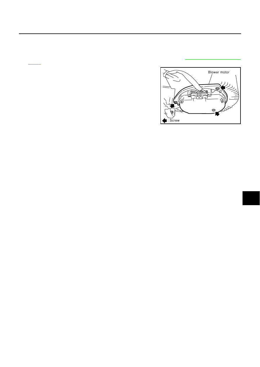
Disconnect blower motor connector. 

3.

Remove mounting screws from blower motor, and then remove
it.

INSTALLATION

Installation is basically the reverse order of removal.

SJIA0280E

ATC-122

INTAKE DOOR MOTOR

INTAKE DOOR MOTOR

PFP:27730

Removal and Installation

AJS000QQ

REMOVAL

1.

Remove, instrument lower assistant cover and instrument rein-
forcement. Refer to 

IP-11, "Removal and Installation"

 .

2.

Remove ECM with bracket attached.

3.

Disconnect intake door motor connector.

4.

Remove mounting screws, and then remove the intake door
motor from the blower unit.

INSTALLATION

Installation is basically the reverse order of removal.

RJIA0280E

IN-CABIN MICROFILTER

ATC-123

C

D

E

F

G

H

I

K

L

M

A

B

ATC

IN-CABIN MICROFILTER

PFP:27277

Removal and Installation

AJS0008G

FUNCTION

Air inside passenger compartment is kept clean at either recircula-
tion or fresh mode by installing in-cabin microfilter into blower unit.

REPLACEMENT TIMING

Replace in-cabin microfilter.
Refer to 

MA-7, "CHASSIS AND BODY MAINTENANCE"

  in SCHEDULE 1 and 

MA-9, "CHASSIS AND BODY

MAINTENANCE"

  in SCHEDULE 2.

Caution label is fixed inside glove box.

REPLACEMENT PROCEDURES

1.

Remove glove box. Refer to 

IP-11, "Removal and Installation"

 .

2.

Remove center cover of glove box cover. 

3.

Remove filter cover.

4.

Take out the in-cabin microfilter from blower unit.

5.

Replace with new one and reinstall on blower unit.

6.

Reinstall the glove box.

RJIA1331E

RJIA1930E

RJIA1332E

ATC-124

HEATER & COOLING UNIT ASSEMBLY

HEATER & COOLING UNIT ASSEMBLY

PFP:27110

Removal and Installation

AJS0008H

REMOVAL

1.

Remove engine cover. Refer to 

EM-12, "ENGINE ROOM COVER"

 .

2.

Use a refrigerant collecting equipment (for HFC-134a) to discharge refrigerant.

3.

Remove tower bar. Refer to 

FSU-6, "FRONT SUSPENSION ASSEMBLY"

 .

4.

Drain coolant from cooling system. Refer to 

MA-12, "Changing

Engine Coolant"

 .

5.

Disconnect two heater hoses from heater core pipe.

6.

Disconnect low-pressure flexible hose and high-pressure pipe
from evaporator.

7.

Remove the instrument panel. Refer to 

IP-11, "Removal and

Installation"

 .

8.

Remove the blower unit. Refer to 

ATC-119, "BLOWER UNIT"

 .

9.

Remove clips of vehicle harness from steering member.

10. Remove the instrument stays (driver side, passenger side).

11. Remove the defroster nozzle and ventilator ducts.

12. Remove the screws from heater & cooling unit.

RJIA1314E

RJIA0115E

RJIA3081E


Content   ..  157  158  159  160   ..