Infiniti M45 (Y34). Manual - part 70
DTC P1721 VEHICLE SPEED SENSOR MTR
AT-165
D
E
F
G
H
I
J
K
L
M
A
B
AT
DTC P1721 VEHICLE SPEED SENSOR MTR
PFP:24814
Description
ACS001CL
The vehicle speed sensor·MTR signal is transmitted from combination meter to TCM by CAN communication
line. The signal functions as an auxiliary device to the revolution sensor when it is malfunctioning. The TCM
will then use the vehicle speed sensor·MTR signal.
CONSULT-II Reference Value
ACS004PE
On Board Diagnosis Logic
ACS001CM
●
This is not an OBD-II self-diagnostic item.
●
Diagnostic trouble code “VHE SPD SE·MTR” with CONSULT-II is detected when TCM does not receive
the proper vehicle speed sensor MTR signal (input by CAN communication) from combination meter.
Possible Cause
ACS001CN
Harness or connectors
(The sensor circuit is open or shorted.)
DTC Confirmation Procedure
ACS001CO
CAUTION:
Always drive vehicle at a safe speed.
NOTE:
If “DTC Confirmation Procedure” has been previously conducted, always turn ignition switch OFF and
wait at least 10 seconds before conducting the next test.
After the repair, perform the following procedure to confirm the malfunction is eliminated.
WITH CONSULT-II
1.
Turn ignition switch ON. (Do not start engine.)
2.
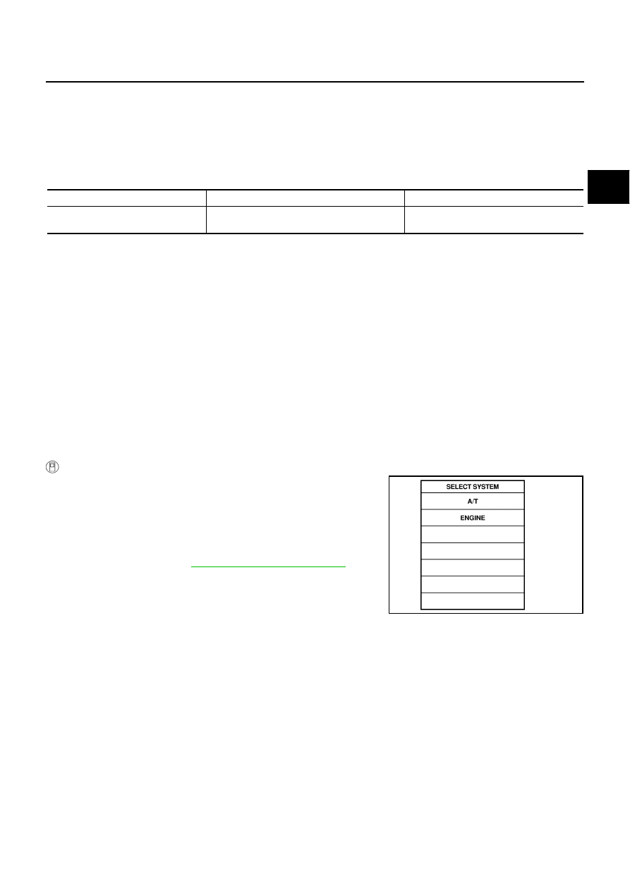
Select “DATA MONITOR” mode for “A/T” with CONSULT-II.
3.
Start engine and maintain the following conditions for at least 5
consecutive seconds.
ACCELE POS: 1/8 or less
VHCL SPEED SE: 30 km/h (17 MPH) or more
4.
AT-166, "Diagnostic Procedure"
Item name
Condition
Display value
VHCL/S SE·MTR
During driving
Approximately matches the speedometer
reading.
SAT014K