Infiniti M45 (Y34). Manual - part 69
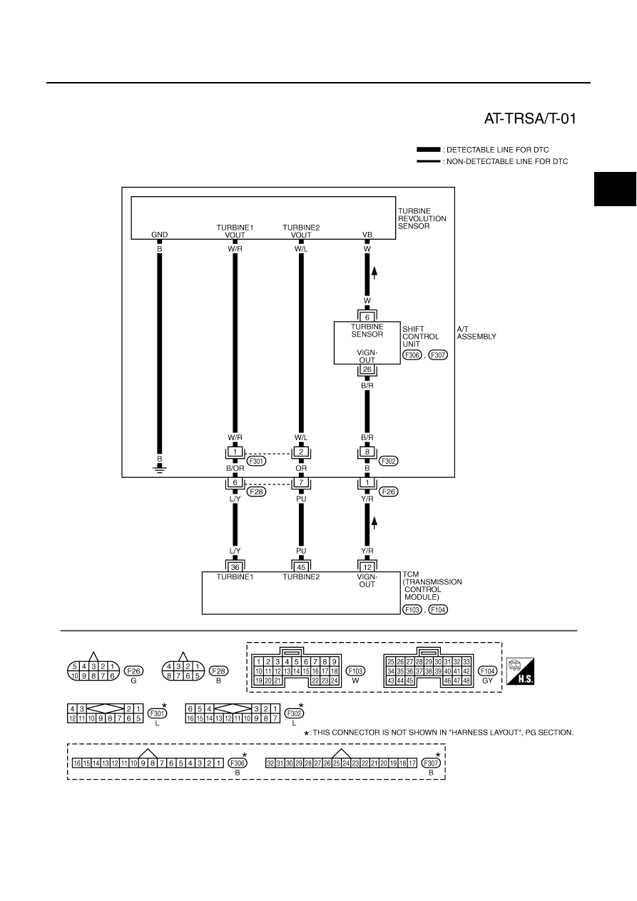
DTC P1716 TURBINE REVOLUTION SENSOR
AT-161
D
E
F
G
H
I
J
K
L
M
A
B
AT
Wiring Diagram — AT — TRSA/T
ACS0048I
TCWA0120E
|
|
|
DTC P1716 TURBINE REVOLUTION SENSOR AT-161 D E F G H I J K L M A B AT Wiring Diagram — AT — TRSA/T ACS0048I TCWA0120E |