Infiniti M45 (Y34). Manual - part 33


  Index      Infiniti     Infiniti M45 (Y34) - service repair manual 2004 year


Search            copyright infringement  


Content   ..  31  32  33  34   ..


Infiniti M45 (Y34). Manual - part 33


A/T FLUID

AT-17

D

E

F

G

H

I

J

K

L

M

A

B

AT

14. Blow compressed air regulated to 5 - 9 kg/cm

2

   (70 - 130 psi) through each steel line from the cooler side

back toward the transmission for 10 seconds to force out any remaining fluid.

15. Ensure all debris is removed from the steel cooler lines.

16. Ensure all debris is removed from the banjo bolts and fittings.

17. Perform 

AT-17, "A/T FLUID COOLER DIAGNOSIS PROCEDURE"

 .

A/T FLUID COOLER DIAGNOSIS PROCEDURE

NOTE:
Insufficient cleaning of the cooler inlet hose exterior may lead to inaccurate debris identification.

1.

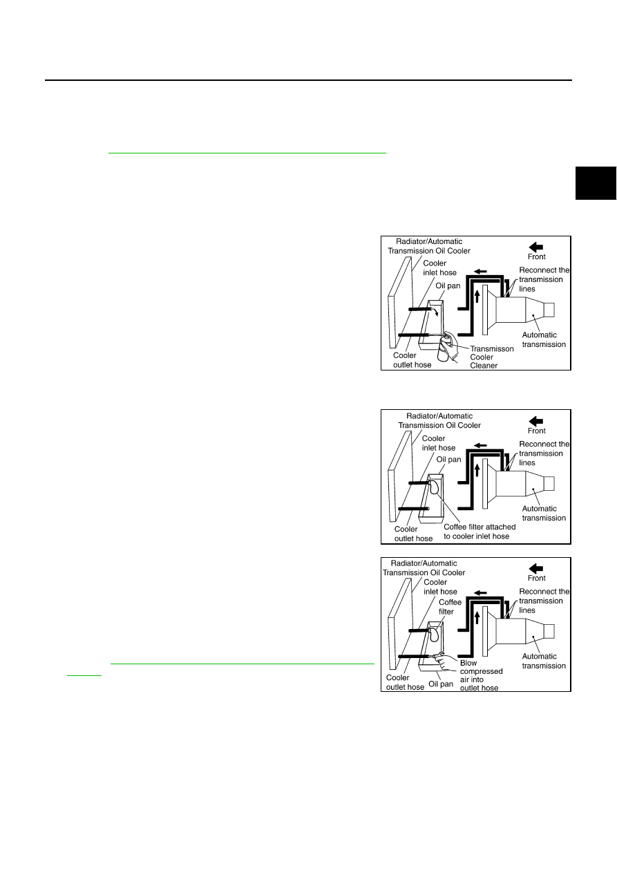
Position an oil pan under the automatic transmission's inlet and outlet cooler hoses.

2.

Clean the exterior and tip of the cooler inlet hose.

3.

Insert the extension adapter hose of a can of the Transmission
Cooler Cleaner (Nissan P/N 999MP-AM006) into the cooler out-
let hose.

CAUTION:

Wear safety glasses and rubber gloves when spraying
the Transmission Cooler Cleaner.

Spray the Transmission Cooler Cleaner only with ade-
quate ventilation.

Avoid contact with eyes and skin.

Do not breath vapors or spray mist.

4.

Hold the hose and can as high as possible and spray the Trans-
mission Cooler Cleaner in a continuous stream into the cooler outlet hose until fluid flows out of the cooler
inlet hose for 5 seconds.

5.

Tie a common white, basket-type coffee filter to the end of the
cooler inlet hose.

6.

Insert the tip of an air gun into the end of the cooler outlet hose.

7.

Wrap a shop rag around the air gun tip and end of cooler outlet
hose.

8.

Blow compressed air regulated to 5 - 9 kg/cm

2

   (70 - 130 psi)

through the cooler outlet hose to force any remaining A/T fluid
into the coffee filter.

9.

Remove the coffee filter from the end of the cooler inlet hose.

10. Perform 

AT-18, "A/T FLUID COOLER INSPECTION PROCE-

DURE"

 .

SCIA3831E

SCIA3833E

SCIA3834E

AT-18

A/T FLUID

A/T FLUID COOLER INSPECTION PROCEDURE

1.

Inspect the coffee filter for debris.

a.

If small metal debris less than 1 mm (0.040 in) in size or metal
powder is found in the coffee filter, this is normal. If normal
debris is found, the A/T fluid cooler/radiator can be re-used and
the procedure is ended.

b.

If one or more pieces of debris are found that are over 1 mm
(0.040 in)  in size and/or peeled clutch facing material is found in
the coffee filter, the fluid cooler is not serviceable. The A/T fluid
cooler/radiator must be replaced and the inspection procedure is
ended. Refer to 

CO-12, "RADIATOR"

   an

CO-15, "RADIATOR

(ALUMINUM TYPE)"

 .

A/T FLUID COOLER FINAL INSPECTION

After performing all procedures, ensure that all remaining oil is cleaned from all components.

SCIA2967E

SCIA5257E

A/T CONTROL SYSTEM

AT-19

D

E

F

G

H

I

J

K

L

M

A

B

AT

A/T CONTROL SYSTEM

PFP:31036

Cross-Sectional View

ACS00198

1.

Front planetary gear

2.

Mid planetary gear

3.

Rear planetary gear

4.

Direct clutch

5.

High and low reverse clutch

6.

Reverse brake

7.

Drum support

8.

Forward brake

9.

Low coast brake

10. Input shaft

11.

Torque converter

12. Oil pump

13. Front brake

14. 3rd one-way clutch

15. Input clutch

16. 1st one-way clutch

17. Control valve

18. Forward one-way clutch

19. Rear extension

20. Intermediate shaft

21. Output shaft

22. Companion flange

SCIA5504E

AT-20

A/T CONTROL SYSTEM

Shift Mechanism

ACS004PW

The automatic transmission uses compact triple planetary gear systems to improve power-transmission effi-
ciency, simplify construction and reduce weight.
It also employs an optimum shift control and super wide gear ratios. They improve starting performance and
acceleration during medium and high-speed operation.

CONSTRUCTION 

FUNCTION OF CLUTCH AND BRAKE 

1.

Front brake

2.

Input clutch

3.

Direct clutch

4.

High and low reverse clutch

5.

Reverse brake

6.

Forward brake

7.

Low coast brake

8.

1st one-way clutch

9.

Forward one-way clutch

10. 3rd one-way clutch

11.

Front sun gear

12. Input shaft

13. Mid internal gear

14.

Front internal gear

15. Rear carrier

16. Rear sun gear

17.

Mid sun gear

18. Front carrier

19. Mid carrier

20.

Rear internal gear

21. Intermediate shaft

22. Output shaft

23.

Parking gear

24. Parking pawl

SCIA3985J

Name of the Part

Abbreviation

Function

Front brake (1)

FR/B

Fastens the front sun gear (11).

Input clutch (2)

I/C

Connects the input shaft (12), the front internal gear (14) and the mid internal 
gear (13).

Direct clutch (3)

D/C

Connects the rear carrier (15) and the rear sun gear (16).

High and low reverse clutch (4)

HLR/C

Connects the mid sun gear (17) and the rear sun gear (16).

Reverse brake (5)

R/B

Fastens the rear carrier (15).

Forward brake (6)

F/B

Fastens the mid sun gear (17).

Low coast brake (7) 

LC/B

Fastens the mid sun gear (17).

1st one-way clutch (8)

1st/OWC

Allows the rear sun gear (16) to turn freely forward relative to the mid sun gear 
(17) but fastens it for reverse rotation.

Forward one-way clutch (9)

Fwd/OWC

Allows the mid sun gear (17) to turn freely in the forward direction but fastens it 
for reverse rotation.

3rd one-way clutch (10)

3rd/OWC

Allows the front sun gear (11) to turn freely in the forward direction but fastens 
it for reverse rotation.


Content   ..  31  32  33  34   ..