Infiniti M45 (Y34). Manual - part 31
PRECAUTIONS
AT-9
D
E
F
G
H
I
J
K
L
M
A
B
AT
Precautions
ACS00191
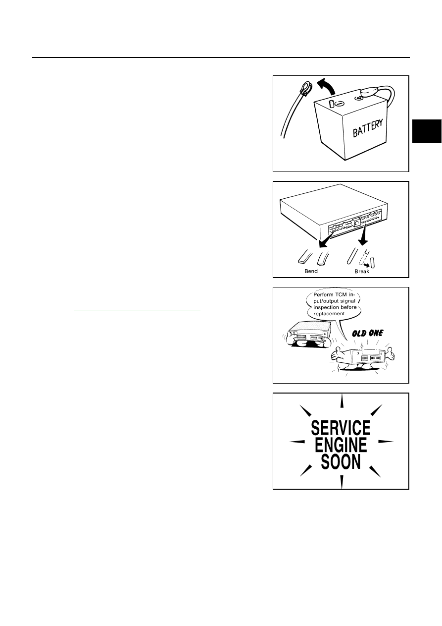
●
Before connecting or disconnecting the TCM harness con-
nector, turn ignition switch OFF and disconnect the battery
cable from the negative terminal. Because battery voltage is
applied to TCM even if ignition switch is turned OFF.
●
When connecting or disconnecting pin connectors into or
from TCM, take care not to damage pin terminals (bend or
break).
Make sure that there are not any bends or breaks on TCM
pin terminal, when connecting pin connectors.
●
Before replacing TCM, perform TCM input/output signal
inspection and make sure whether TCM functions properly
or not.
.
●
After performing each TROUBLE DIAGNOSIS, perform
“DTC (Diagnostic Trouble Code) CONFIRMATION PROCE-
DURE”.
If the repair is completed the DTC should not be displayed
in the “DTC CONFIRMATION PROCEDURE”.
SEF289H
SEF291H
MEF040DA
SEF217U