Infiniti M35/M45 Y50. Manual - part 209
 

  Index      Infiniti     Infiniti M35/M45 Y50 - service repair manual 2007 year


Search            copyright infringement  


Content   ..  207  208  209  210   ..


Infiniti M35/M45 Y50. Manual - part 209


TERMINALS AND REFERENCE VALUE FOR CONTROL UNIT

AV-213

[WITH MOBILE ENTERTAINMENT SYSTEM]

C

D

E

F

G

H

I

J

L

M

A

B

AV

33

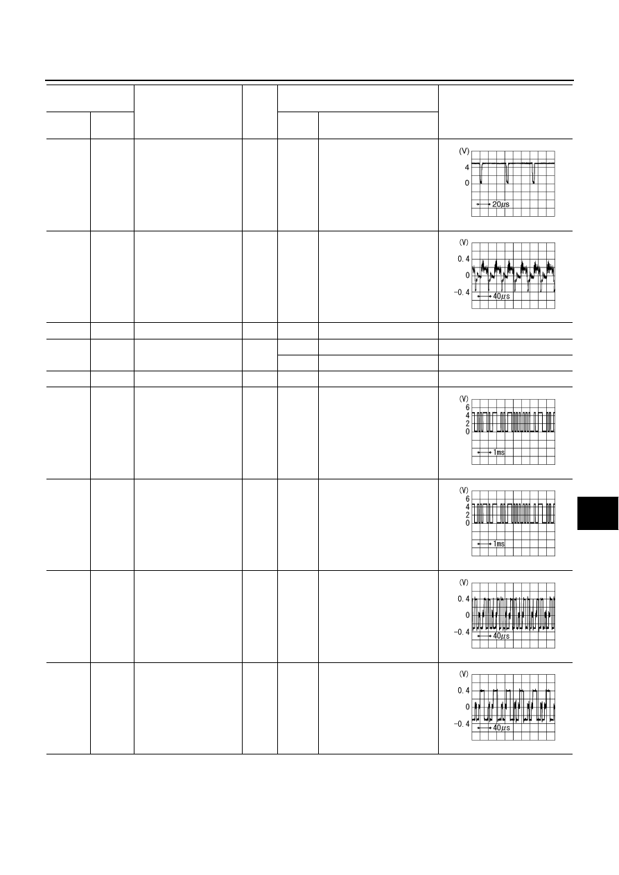
(R)

Ground

Image synchronizing sig-
nal (rear)

Output

ON

Rear display
RGB image

34

(G)

Ground

Composite image signal
(rear)

Output

ON

Rear display
DVD image

35

–

Shield

–

–

–

–

36

(O)

Ground

Ignition signal 
(rear display)

Output

ON

–

Approx. 0 V

ACC

–

Approx. 5 V

38

–

Shield

–

–

–

–

39

(W)

Ground

Communication signal
(DISP-DIST)

Input

ON

Image quality adjustment

40

(O)

Ground

Communication signal
(DIST-DISP)

Output

ON

Image quality adjustment

44

(L/G)

47

(W/L)

RGB signal (R: red)

Input

ON

Start confirmation/adjust-
ment mode, and then dis-
play color bar by selecting 
“Color Spectrum Bar” on 
DISPLAY DIAGNOSIS 
screen.

45

(O/L)

47

(W/L)

RGB signal (G: green)

Input

ON

Start confirmation/adjust-
ment mode, and then dis-
play color bar by selecting 
“Color Spectrum Bar” on 
DISPLAY DIAGNOSIS 
screen.

Terminal

(Wire color)

Item

Signal

input/

output

Condition

Reference value

+

–

Ignition

Switch

Operation

SKIB0825E

SKIB2251J

PKIB5039J

PKIB5039J

SKIB2238J

SKIB2236J

AV-214

[WITH MOBILE ENTERTAINMENT SYSTEM]

TERMINALS AND REFERENCE VALUE FOR CONTROL UNIT

46

(L/Y)

47

(W/L)

RGB signal (B: blue)

Input

ON

Start confirmation/adjust-
ment mode, and then dis-
play color bar by selecting 
“Color Spectrum Bar” on 
DISPLAY DIAGNOSIS 
screen.

47

(W/L)

Ground

RGB ground

–

ON

–

Approx. 0 V

48

(G)

Ground

RGB area (YS) signal

Input

ON

When inputting RGB image.

Approx. 5 V

Set the selector lever in R 
position, and then display 
the rear view  image.

49

(W)

Ground

Horizontal synchronizing 
(HP) signal

Output

ON

–

50

(R)

Ground

Vertical synchronizing 
(VP) signal

Output

ON

–

51

(B)

Ground

RGB synchronizing sig-
nal

Input

ON

–

52

–

Shield

–

–

–

–

53

(B)

Ground

Ground

–

ON

–

Approx. 0 V

54

(L)

Ground

Battery power supply

Input

OFF

–

Battery voltage

55

(V)

Ground

ACC power supply

Input

ACC

–

Battery voltage

56

(G)

Ground

Ignition signal

Input

ON

–

Battery voltage

57

(W)

Ground

Remote control receiver  
VCC

Output

ON

–

Approx. 5 V

Terminal

(Wire color)

Item

Signal

input/

output

Condition

Reference value

+

–

Ignition

Switch

Operation

SKIB2237J

PKIB4948J

SKIB0825E

SKIB0823E

SKIB0825E

TERMINALS AND REFERENCE VALUE FOR CONTROL UNIT

AV-215

[WITH MOBILE ENTERTAINMENT SYSTEM]

C

D

E

F

G

H

I

J

L

M

A

B

AV

Front Display Unit

NKS004AQ

58

(B)

Ground

Remote control signal

Output

ON

Rear seat remote controller 
operation

59

–

Shield

–

–

–

–

60

(L)

Ground

Headphone amp ON sig-
nal

Input

ON

Headphone mode is ON.

Approx. 4 V

Headphone mode is OFF.

Approx. 0 V

Terminal

(Wire color)

Item

Signal

input/

output

Condition

Reference value

+

–

Ignition

Switch

Operation

PKIB6988J

Terminal

(Wire color)

Item

Signal

input/

output

Condition

Reference value

+

–

Ignition 

switch

Operation

1

(B)

8

(G)

RGB signal (R: red)

Input

ON

Start confirmation/adjust-
ment mode, and then dis-
play color bar by selecting 
“Color Spectrum Bar” on 
DISPLAY DIAGNOSIS 
screen.

2

(L/G)

Ground

RGB area (YS) signal

Input

ON

When inputting RGB image.

Approx. 5 V

Set the selector lever in R 
position, and then display 
the rear view  image.

3

(W)

8

(G)

RGB signal (G: green)

Input

ON

Start confirmation/adjust-
ment mode, and then dis-
play color bar by selecting 
“Color Spectrum Bar” on 
DISPLAY DIAGNOSIS 
screen.

4

(W/L)

Ground

Horizontal synchronizing 
(HP) signal

Output

ON

–

SKIB2238J

PKIB4948J

SKIB2236J

SKIB0825E

AV-216

[WITH MOBILE ENTERTAINMENT SYSTEM]

TERMINALS AND REFERENCE VALUE FOR CONTROL UNIT

5

(R)

8

(G)

RGB signal (B: blue)

Input

ON

Start confirmation/adjust-
ment mode, and then dis-
play color bar by selecting 
“Color Spectrum Bar” on 
DISPLAY DIAGNOSIS 
screen.

6

(O/L)

Ground

Vertical synchronizing 
(VP) signal

Output

ON

–

7

(L/Y)

Ground

RGB synchronizing sig-
nal

Output

ON

–

8

(G)

Ground

RGB ground

–

ON

–

Approx. 0 V

10

–

Shield

–

–

–

–

11

(Y)

Ground

Camera image signal

Input

ON

Set the selector in R posi-
tion, and then display the 
rear view image.

12

–

Shield

–

–

–

–

13

(B/R)

Ground

Composite synchroniz-
ing signal

Input

ON

–

14

–

Shield

–

–

–

–

15

(BR)

Ground

Composite image signal

Input

ON

DVD image

Terminal

(Wire color)

Item

Signal

input/

output

Condition

Reference value

+

–

Ignition 

switch

Operation

SKIB2237J

SKIB0823E

SKIB0826E

SKIB0827E

SKIA0187E

SKIB2251J


Content   ..  207  208  209  210   ..