Infiniti F50. Manual - part 816


  Index      Infiniti     Infiniti F50 - service repair manual 2006 year


Search            


Content   ..  814  815  816  817   ..


Infiniti F50. Manual - part 816


DIAGNOSIS SENSOR UNIT

SRS-51

C

D

E

F

G

I

J

K

L

M

A

B

SRS

DIAGNOSIS SENSOR UNIT

PFP:28556

Removal and Installation

EHS0008W

REMOVAL

CAUTION:

Before servicing SRS, turn the ignition switch off, disconnect both battery cables and wait at least
3 minutes.

1.

Disconnect each harness connector for the air bag module and
seat belt pre-tensioner.

2.

Remove center console. Refer to 

IP-10, "INSTRUMENT PANEL

ASSEMBLY"

 .

3.

Disconnect diagnosis sensor unit connector.
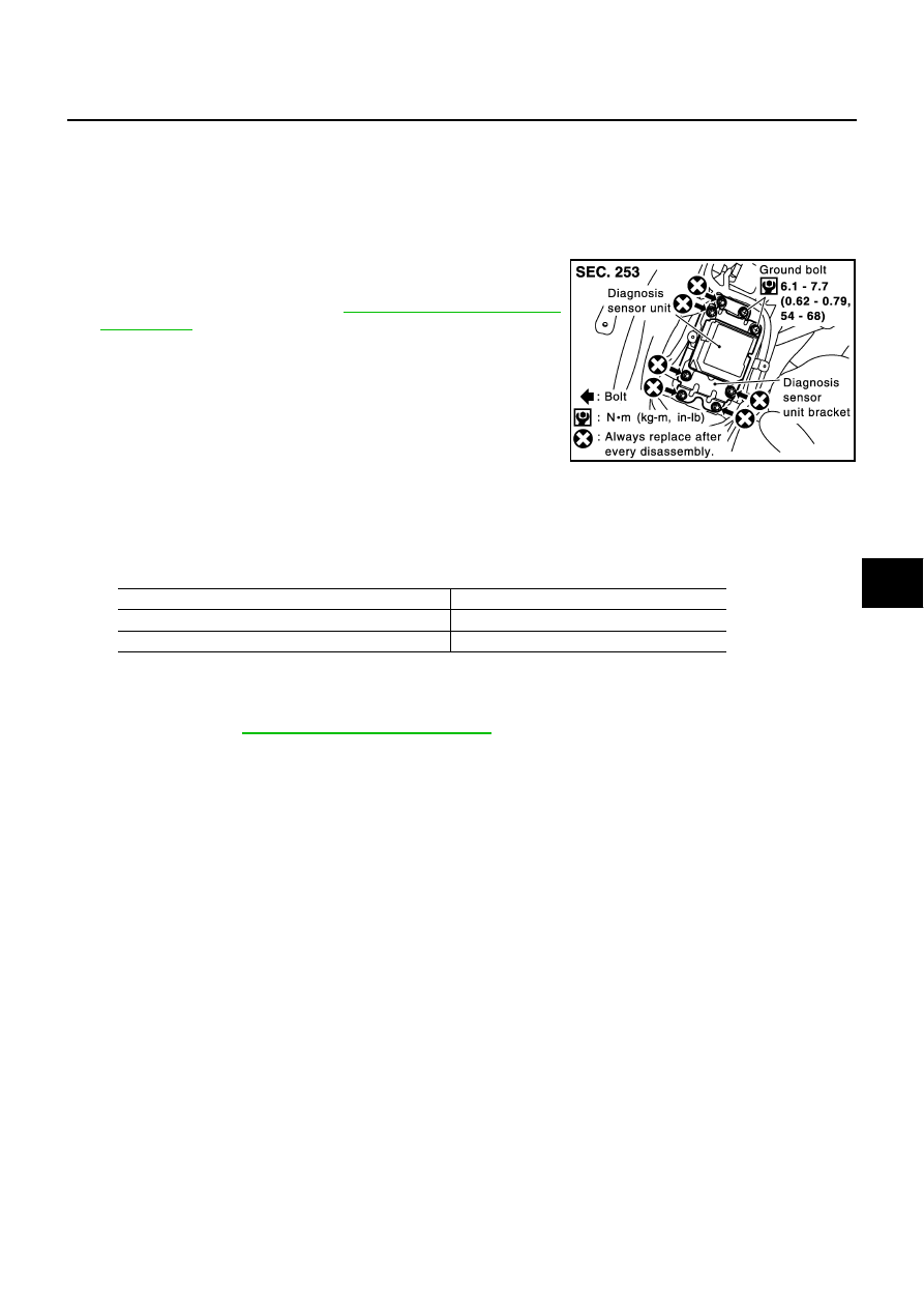
4.

Remove the installation bolts.

CAUTION:

Do not use old bolts. Replace with new ones.

Check diagnosis sensor unit brackets to ensure it is free of
deformities, dents, cracks or rust. If it shows any visible
signs of damage, replace it with new one.

Replace diagnosis sensor unit if it has been dropped or sustained an impact.

INSTALLATION

To install, reverse the removal procedure sequence.
Concerning the diagnosis sensor unit tightening torque as follows;

CAUTION:

Check the diagnosis sensor unit for proper installation.

After replacement of diagnosis sensor unit, perform self-diagnosis to check that no malfunction is
detected. Refer to 

SRS-20, "SRS Operation Check"

 .

ECU DISCRIMINATED NO.

After replacing the diagnosis sensor unit, confirm that the diagnosis sensor unit identification No. is F342.

PHIA0272E

Bolts type

Tightening torque

TORX bolts (For TAMPER RESISTANT T50 size)

14.7 - 24.5 N.m (1.5 - 2.5 kg-m, 11 - 18 ft-lb)

Hexagon bolts

19.6 - 29.4 N.m (2.0 - 2.9 kg-m, 15 - 21 ft-lb)

SRS-52

DISPOSAL OF AIR BAG MODULE AND SEAT BELT PRE-TENSIONER

DISPOSAL OF AIR BAG MODULE AND SEAT BELT PRE-TENSIONER

PFP:00014

Caution for Air Bag Module and Seat Belt Pre-tensioner 

EHS0009A

Before disposing of air bag module and seat belt pre-tensioner, or vehicles equipped with such systems,
deploy the systems. If such systems have already been deployed due to an accident, dispose of them as
indicated in 

SRS-58, "DISPOSING OF AIR BAG MODULE AND SEAT BELT PRE-TENSIONER"

 .

When deploying the air bag module and seat belt pre-tensioner, always use the Special Service Tool;
Deployment tool [SST: KV99106400 (J38381)].

When deploying the air bag module and seat belt pre-tensioner, stand at least 5 m (16 ft) away from the
deployment component.

When deploying air bag module and seat belt pre-tensioner, a fairly loud noise is made, followed by
smoke being released. The smoke is not poisonous, however, be careful not to inhale smoke since it irri-
tates the throat and can cause choking.

Always activate one air bag module at a time.

Due to heat, leave air bag module unattended for more than 30 minutes after deployment. Also leave seat
belt pre-tensioner unattended for more than 10 minutes after deployment.

Be sure to wear gloves when handling a deployed air bag module and seat belt pre-tensioner.

Never apply water to the deployed air bag module and seat belt pre-tensioner.

Wash your hands clean after finishing work.

Place the vehicle outdoors with an open space of at least 6 m (20 ft) on all sides when deploying air bag
module and seat belt pre-tensioner while mounted in vehicle.

Use a voltmeter to make sure the vehicle battery is fully charged.

Do not dispose of the air bag module and seat belt pre-tensioner un-deployed.

CHECKING DEPLOYMENT TOOL
Connecting to Battery

CAUTION:

The battery must show voltage of 9.6V or more.
Remove the battery from the vehicle and place it on dry wood blocks
approximately 5 m (16 ft) away from the vehicle.

Wait 3 minutes after the vehicle battery is disconnected before
proceeding.

Connect red clip of deployment tool to battery positive terminal
and black clip to negative terminal.

Make sure the polarity is correct. The right side lamp in the tool,
marked “deployment tool power”, should glow with a green
light. If the right side lamp glows red, reverse the connections
to the battery.

Deployment Tool Check

Press the deployment tool switch to the ON position. The left side
lamp in the tool, marked “air bag connector voltage” should illumi-
nate. If it does not illuminate, replace the tool.

SRS019

SBF266H

DISPOSAL OF AIR BAG MODULE AND SEAT BELT PRE-TENSIONER

SRS-53

C

D

E

F

G

I

J

K

L

M

A

B

SRS

Air Bag Deployment Tool Lamp Illumination Chart (Battery connected)

*: If this lamp glows red, the tool is connected to the battery incorrectly. Reverse the connections and make sure the lamp glows green.

DEPLOYMENT PROCEDURES FOR AIR BAG MODULE (OUTSIDE OF VEHICLE)

Unless the vehicle is being scrapped, deploying the air bag in the
vehicle is not recommended. This may cause damage to the vehicle
interior.
Anchor air bag module bracket [SST: KV99105300 (J41246)] in a
vise secured to a firm foundation during deployment.

Deployment of Driver Air Bag Module (Outside of vehicle)

1.

Using wire, secure air bag module to air bag module bracket
[SST: KV99105300 (J41246)] at two places.

CAUTION:

Use wire of at least 1 mm (0.04 in) diameter.

2.

Firmly secure air bag module bracket [SST: KV99105300
(J41246)] with air bag module attached, in a vise.

3.

Connect deployment tool adapter (SST: J38381-70) to deploy-
ment tool [SST: KV99106400 (J38381)] to air bag module con-
nector.

4.

Connect red clip of deployment tool to battery positive terminal
and black clip to negative terminal.

5.

The lamp on the right side of the tool, marked “deployment tool
power”, should glow green, not red.

6.

Press the button on the deployment tool. The left side lamp on
the tool, marked “air bag connector voltage”, will illuminate and
the air bag module will deploy.

CAUTION:

When deploying the driver air bag module, stand at least 5 m
(16 ft) away from the air bag module.

Switch operation

Left side lamp, green*

“AIR BAG CONNECTOR 

VOLTAGE”

Right side lamp, green*

“DEPLOYMENT TOOL 

POWER”

OFF

OFF

ON

ON

ON

ON

SRS232-C

SRS233

SRS906

SRS235

SRS-54

DISPOSAL OF AIR BAG MODULE AND SEAT BELT PRE-TENSIONER

Deployment of Front Passenger Air Bag Module (Outside of vehicle)

1.

Make an 8.5 mm (0.335 in) diameter hole in air bag module
bracket [SST: KV99105300 (J41246)] at the position shown in
figure at right.

2.

Firmly secure air bag module bracket [SST: KV99105300
(J41246)] in a vise.

3.

Match the two holes in air bag module bracket (held in vise) and
front passenger air bag module and fix them with two bolts [M8 

×

25 - 30 mm (0.98 - 1.18 in)].

CAUTION:

If a gap exists between front passenger air bag module and
air bag module bracket, use a piece of wood inserted in the
gap to stabilize the air bag module.

4.

Connect deployment tool adapter (SST: J38381-65) to deploy-
ment tool [SST: KV99106400 (J38381)] connector and front pas-
senger air bag module connector.

5.

Connect red clip of deployment tool to battery positive terminal
and black clip to negative terminal.

6.

The lamp on the right side of the tool, marked “deployment tool
power”, should glow green, not red.

7.

Press the button on the deployment tool. The left side lamp on
the tool, marked “air bag connector voltage”, will illuminate and
the air bag module will deploy.

CAUTION:

When deploying the front passenger air bag module, do not
stand on the deploying side.

Stand at least 5 m (16 ft) away from the air bag module.

SRS232-C

SHIA0195E

SHIA0196E

SRS020-B


Content   ..  814  815  816  817   ..