Infiniti F50. Manual - part 716
REAR DRIVE SHAFT
RAX-9
C
E
F
G
H
I
J
K
L
M
A
B
RAX
REAR DRIVE SHAFT
PFP:39600
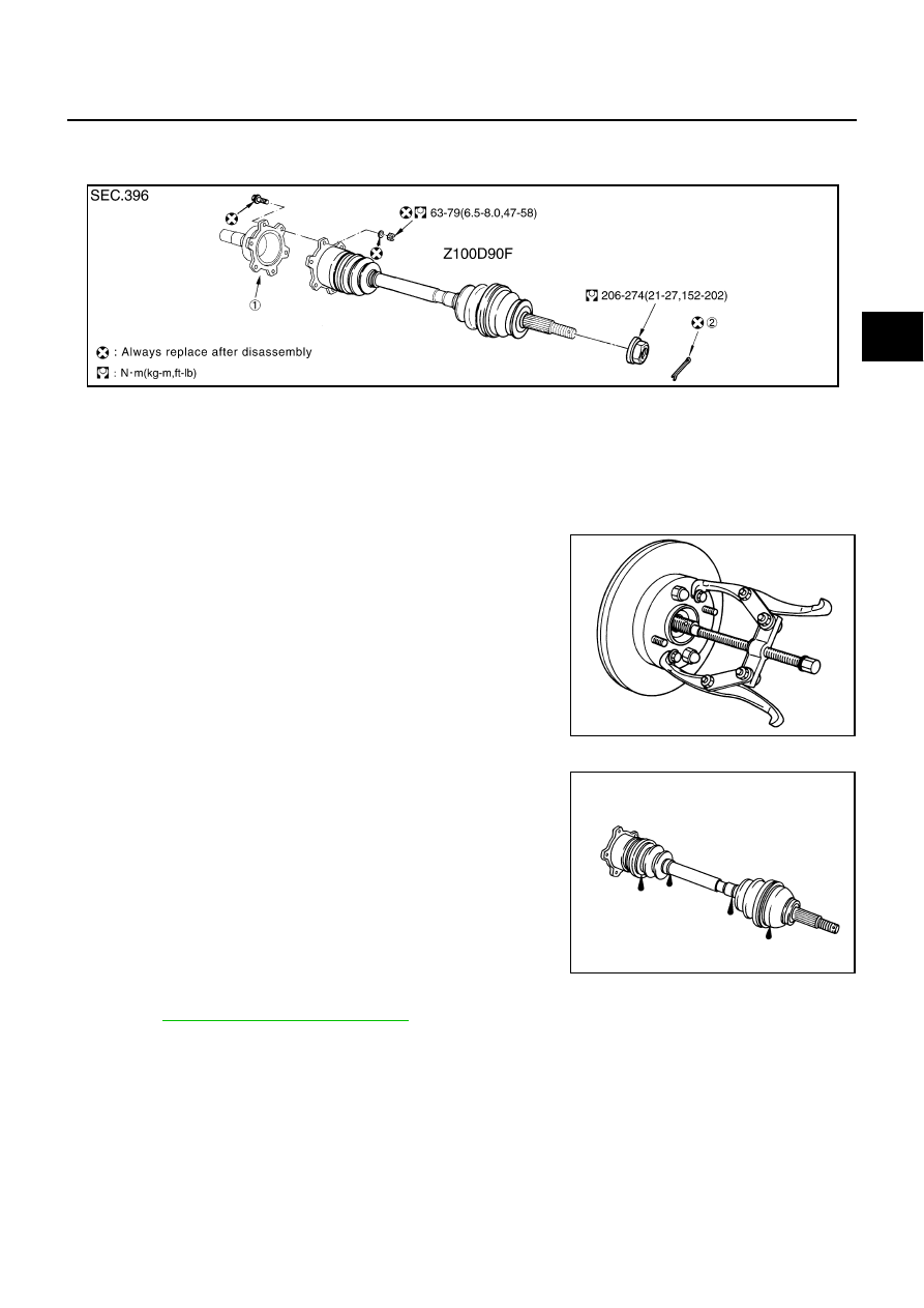
Removal and Installation
EDS000WQ
REMOVAL
1.
Remove tire with power tool.
2.
Remove cotter pin. Then remove lock nut from drive shaft.
3.
Remove exhaust center tube.
4.
Remove fixing nuts and bolts between final drive and drive shaft.
5.
Using a puller (suitable tool), remove drive shaft from axle.
CAUTION:
When removing drive shaft, do not apply an excessive
angle to drive shaft joint. Also be careful not to excessively
extend slide joint.
INSPECTION AFTER REMOVAL
●
Move joint in the up/down, left/right, and axial direction. Check
for any rough movement or significant looseness.
●
Check boot for cracks or other damage, and also for grease
leakage.
●
If a trouble is found, disassemble drive shaft, and then replace
with new one.
INSTALLATION
●
Refer to
RAX-9, "Removal and Installation"
for tightening torque. Tighten in the reverse order of removal.
CAUTION:
Refer to component parts location and do not reuse non-reusable parts.
1.
Side flange
2.
Cotter pin
SDIA1174E
SDIA0972J
RAA0030D