Infiniti F50. Manual - part 682


  Index      Infiniti     Infiniti F50 - service repair manual 2006 year


Search            


Content   ..  680  681  682  683   ..


Infiniti F50. Manual - part 682


PARKING BRAKE SYSTEM

PB-3

C

D

E

G

H

I

J

K

L

M

A

B

PB

PARKING BRAKE SYSTEM

PFP:36010

On-Vehicle Service

EFS000GP

INSPECTION

While depressing parking brake pedal to specified amount of
force, check that pedal stroke is within the range of specified
stroke amount.

Check that warning lamp comes on when parking brake pedal is
depressed with in one notch.
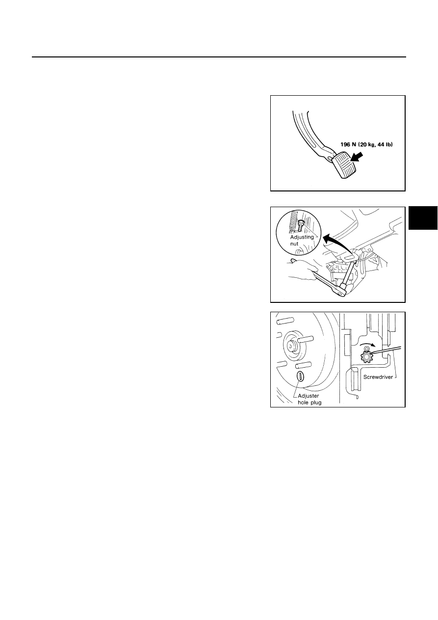
ADJUSTMENT

1.

Insert a deep-well socket wrench to rotate self-locking nut to
loosen cable sufficiently. Then, after returning pedal completely,
adjust the clearance of rear shoes.

2.

Remove road wheels.

3.

Using a wheel nut, fix the disc to hub preventing it from tilting.

4.

Remove adjuster hole plug installed on disc. Using a screw-
driver, turn disc to clock wise as shown in figure until disc is
locked. After locking, turn adjuster to opposite direction by 5 or 6
notches.

5.

Rotate disc to make sure that there is no drag. Then install
adjuster hole plug.

6.

After adjusting the clearance of rear shoes, with no drag on rear
brake, adjust cable as follows:

a.

Operate pedal 10 or more times with the force of 294 N (30 kg,
66 lb).

b.

Depress pedal until a deep-well socket can be inserted. Insert
deep-well socket, and rotate self-locking nut to adjust pedal stroke.

CAUTION:

Do not reuse self-locking nut after removing it.

c.

After operating pedal 3 to 4 times with the force of 196 N (20 kg, 44 lb), make sure that pedal stroke is
within specified value.

d.

With pedal completely returned, make sure that there is no drag on rear brake.

Number of notches

: 4 - 5

SBR695A

SBR051C

SBR046C

PB-4

PARKING BRAKE CONTROL

PARKING BRAKE CONTROL

PFP:36010

Components

EFS000O2

Removal and Installation

EFS000O3

REMOVAL

1.

Remove console.Refer to 

IP-10, "INSTRUMENT PANEL ASSEMBLY"

 .

2.

Remove self-locking nut from device assembly.

3.

Remove exhaust center tube.Refer to 

EX-3, "Removal and Installation"

 .

4.

Remove propeller shaft.Refer to 

PR-3, "Removal and Installation"

 . 

5.

Remove rear disc caliper and disc rotor.

6.

Remove parking brake shoe, and remove rear cable from toggle lever.

7.

Remove cable mounting nuts.

8.

Remove right and left rear cable from vehicle.

9.

Remove air bag sensor unit with sensor mount bracket. Refer to 

SRS-51, "Removal and Installation"

 .

10. Remove front cable mounting nuts and bolts, and remove front cable from vehicle.

11. Remove mounting bolts of release cable and device assembly, and remove device assembly from vehicle.

1.

Parking brake pedal Assembly

2.

Return spring

3.

Warning lamp switch

4.

Front cable

5.

Lock plate

6.

Clamp

7.

Return spring

8.

RH rear cable

9.

LH rear cable

10.

Stopper pin

SFIA0137E

PARKING BRAKE CONTROL

PB-5

C

D

E

G

H

I

J

K

L

M

A

B

PB

INSTALLATION

1.

Install in the reverse order of removal. Tighten mounting bolts and nuts to the specified torque.

CAUTION:

Do not reuse self-locking nut of parking cable.

2.

Adjust clearance of parking brake shoes.

Inspection

EFS000O4

Check device assembly for bend, damage, and cracks. Replace if necessary.

Check cable and equalizer for wear and damage. 

Check warning lamp switch. Replace if necessary.

Check each part for deformation, or damage by contact with other parts. Replace if necessary.

PB-6

PARKING BRAKE SHOE

PARKING BRAKE SHOE

PFP:44060

Components

EFS000O5

Removal and Installation

EFS000O6

REMOVAL

WARNING:

Clean brakes with a vacuum dust collector to minimize the hazard of airborne particles or other mate-
rials.

CAUTION:

Remove wheel, and remove disc rotor with parking pedal completely returned.

If disc rotor cannot be removed, remove as follows:

1.

Fix the disc rotor with wheel nut, and remove adjuster hole plug.
Using a screwdriver, rotate star wheel on the adjuster assembly
in the direction B to loosen, and retract brake shoes.

2.

Remove plug.

3.

Insert flat-tip screwdriver through plug. Turn adjuster to make
clearance between brake shoe and drum.

1.

Toggle lever

2.

Stopper pin

3.

Return spring

4.

Shoe

5.

Adjuster spring

6.

Anti-rattle spring

7.

Retainer

8.

Anti-rattle pin

9.

Adjuster assembly

SFIA0152E

SFIA1000E


Content   ..  680  681  682  683   ..