Infiniti F50. Manual - part 647
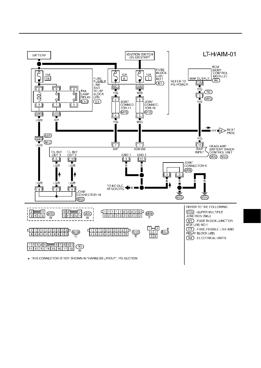
HEADLAMP AIMING CONTROL
LT-55
C
D
E
F
G
H
I
J
L
M
A
B
LT
HEADLAMP AIMING CONTROL
PFP:26010
Wiring Diagram — H/AIM —
EKS000T7
TKWM0398E
|
|
|
HEADLAMP AIMING CONTROL LT-55 C D E F G H I J L M A B LT HEADLAMP AIMING CONTROL PFP:26010 Wiring Diagram — H/AIM — EKS000T7 TKWM0398E |