Infiniti F50. Manual - part 626


  Index      Infiniti     Infiniti F50 - service repair manual 2006 year


Search            


Content   ..  624  625  626  627   ..


Infiniti F50. Manual - part 626


CAN SYSTEM (FOR VDC MODELS)

LAN-33

[CAN]

C

D

E

F

G

H

I

J

L

M

A

B

LAN

ECM Circuit Check

EKS003LD

1. 

CHECK CONNECTOR

1.

Turn ignition switch OFF.

2.

Check following terminals and connector for damage, bend and loose connection. (control module-side
and harness-side)

ECM.

Harness connector F34.

Harness connector E34.

OK or NG

OK

>> GO TO 2.

NG

>> Repair terminal or connector.

2. 

CHECK HARNESS FOR OPEN CIRCUIT

1.

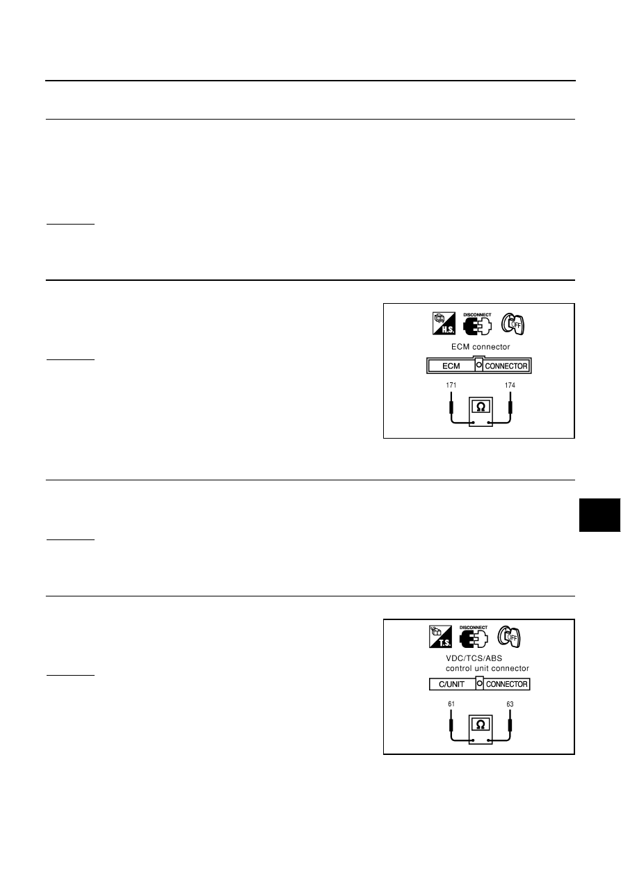
Disconnect ECM connector.

2.

Check resistance between ECM harness connector F102 termi-
nals 174(LG/B) and 171(P/B).

OK or NG

OK

>> Replace ECM.

NG

>> Repair harness between VDC/TCS/ABS control unit and

ECM.

VDC/TCS/ABS Control Unit Circuit Check

EKS003LE

1. 

CHECK CONNECTOR

1.

Turn ignition switch OFF.

2.

Check the terminals and connector of VDC/TCS/ABS control unit for damage, bend and loose connection.
(control unit-side and harness-side)

OK or NG

OK

>> GO TO 2.

NG

>> Repair terminal or connector.

2. 

CHECK HARNESS FOR OPEN CIRCUIT

1.

Disconnect VDC/TCS/ABS control unit connector.

2.

Check resistance between VDC/TCS/ABS control unit harness
connector E218 terminals 61(LG/B) and 63(P/B).

OK or NG

OK

>> Replace VDC/TCS/ABS control unit.

NG

>> Repair harness between ECM and VDC/TCS/ABS con-

trol unit.

174(LG/B) – 171(P/B) 

: Approx. 108 – 132

PKIA0279E

61(LG/B) – 63(P/B) 

: Approx. 54 – 66

PKIA0280E

LAN-34

[CAN]

CAN SYSTEM (FOR VDC MODELS)

Steering Angle Sensor Circuit Check

EKS003LF

1. 

CHECK CONNECTOR

1.

Turn ignition switch OFF.

2.

Check the terminals and connector of steering angle sensor for damage, bend and loose connection.(sen-
sor-side and harness-side)

OK or NG

OK

>> GO TO 2.

NG

>> Repair terminal or connector.

2. 

CHECK HARNESS FOR OPEN CIRCUIT

1.

Disconnect steering angle sensor connector.

2.

Check resistance between steering angle sensor harness con-
nector M52 terminals 4(LG/B) and 5(P/B).

OK or NG

OK

>> Replace steering angle sensor.

NG

>> Repair harness between combination meter and steer-

ing angle sensor.

Combination Meter Circuit Check

EKS003LG

1. 

CHECK CONNECTOR

1.

Turn ignition switch OFF.

2.

Check terminals and connector of combination meter for damage, bend and loose connection.(meter-side
and harness-side)

OK or NG

OK

>> GO TO 2.

NG

>> Repair terminal or connector.

2. 

CHECK HARNESS FOR OPEN CIRCUIT

1.

Disconnect combination meter connector.

2.

Check resistance between combination meter harness connec-
tor M41 terminals 15 (LG/B) and 16 (P/B).

OK or NG

OK

>> Replace combination meter.

NG

>> Repair harness between steering angle sensor and

combination meter.

4(LG/B) – 5(P/B) 

: Approx. 54 – 66

SKIA3777E

15(LG/B) – 16(P/B) 

: Approx. 54 – 66

PKIA0282E

CAN SYSTEM (FOR VDC MODELS)

LAN-35

[CAN]

C

D

E

F

G

H

I

J

L

M

A

B

LAN

TCM Circuit Check

EKS003LH

1. 

CHECK CONNECTOR

1.

Turn ignition switch OFF.

2.

Check following terminals and connector for damage, bend and loose connection.(control module-side
and harness-side)

TCM.

Harness connector F105.

Harness connector M135.

OK or NG

OK

>> GO TO 2.

NG

>> Repair terminal or connector.

2. 

CHECK HARNESS FOR OPEN CIRCUIT

1.

Disconnect TCM connector.

2.

Check resistance between TCM harness connector F103 termi-
nals 6 (LG/B) and 7(P/B).

OK or NG

OK

>> Replace TCM.

NG

>> Repair harness between combination meter and TCM.

CAN Communication Circuit Check

EKS003LI

1. 

CHECK CONNECTOR

1.

Turn ignition switch OFF.

2.

Check following terminals and connector for damage, bend and loose connection.(control module-side,
control unit-side, meter-side, sensor-side and harness-side)

TCM.

Combination meter.

Steering angle sensor.

VDC/TCS/ABS control unit.

ECM.

Between TCM and ECM.

OK or NG

OK

>> GO TO 2.

NG

>> Repair terminal or connector.

6(LG/B) – 7(P/B) 

: Approx. 108 – 132

PKIA0283E

LAN-36

[CAN]

CAN SYSTEM (FOR VDC MODELS)

2. 

CHECK HARNESS FOR SHORT CIRCUIT

1.

Disconnect TCM connector and harness connector F105.

2.

Check continuity between TCM harness connector F103 termi-
nals 6 (LG/B) and 7(P/B).

OK or NG

OK

>> GO TO 3.

NG

>> Repair harness between TCM and harness connector

F105.

3. 

CHECK HARNESS FOR SHORT CIRCUIT

Check continuity between TCM harness connector F103 terminals 6
(LG/B), 7 (P/B) and ground.

OK or NG

OK

>> GO TO 4.

NG

>> Repair harness between TCM and harness connector

F105.

4. 

CHECK HARNESS FOR SHORT CIRCUIT

1.

Disconnect combination meter connector, steering angle sensor connector and harness connector M6.

2.

Check continuity between Data Link Connector M31 terminals 6
(LG/B) and 3(P/B).

OK or NG

OK

>> GO TO 5.

NG

>>

Repair harness between harness connector M6 and
harness connector M135.

Repair harness between harness connector M6 and
Data Link Connector.

Repair harness between harness connector M6 and
combination meter.

Repair harness between harness connector M6 and steering angle sensor.

6(LG/B) – 7(P/B) 

: Continuity should not exist.

PKIA0283E

6(LG/B) – ground

: Continuity should not exist.

7(P/B) – ground

: Continuity should not exist.

PKIA0284E

6(LG/B) – 3(P/B) 

: Continuity should not exist.

PKIA0285E


Content   ..  624  625  626  627   ..