Infiniti F50. Manual - part 604
 

  Index      Infiniti     Infiniti F50 - service repair manual 2006 year


Search            


Content   ..  602  603  604  605   ..


Infiniti F50. Manual - part 604


REVERSE INTERLOCK DOOR MIRROR SYSTEM

GW-87

C

D

E

F

G

H

J

K

L

M

A

B

GW

( ): Passenger side door mirror control unit.

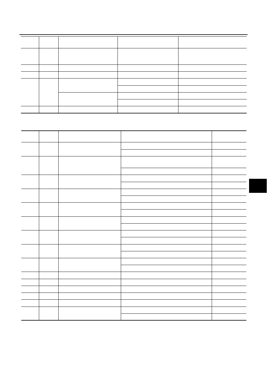
Terminals and Reference Values for BCM 

EIS0014P

6

G

Mirror sensor LH / RH signal

When motor is activated 
(LH or RH)

Changes between 

4 (close to right edge) – 0.5 (close to 

left edge)

7

R/B

Data line A-3

8

L

BAT power supply

Battery voltage

9

PU/W

(OR)

Mirror motor DOWN signal

When motor is activated (DOWN)

Battery voltage

When motor is not activated

0

Mirror motor RH signal

When motor is activated (RH)

Battery voltage

When motor is not activated

0

10

B

Ground

0

TERMI-

NAL

WIRE 

COLOR

ITEM

CONDITION

VOLTAGE [V]

(Approx.)

TERMI-

NAL

WIRE

COLOR

ITEM

CONDITION

VOLTAGE [V]

(Approx.)

21

SB

Door mirror LH / RH switching 
signal – RH

Set the door mirror control switch to right position.

0

Other than above

5

24

BR/Y

Door mirror LH / RH switching 
signal – LH

Set the door mirror remote control switch to left 

position.

0

Other than above

5

25

G/R

Door mirror remote control switch 
signal – LH operation

Set the either LH/RH door mirror face to left.

0

Other than above

5

29

LG/R

Door mirror remote control switch 
signal – RH operation

Set the either LH/RH door mirror face to right. 

0

Other than above

5

32

L/W

Door mirror remote control switch 
signal – Upward

Set the either LH/RH door mirror face upward.

0

Other than above

5

34

P/L

Door mirror remote control switch 
signal – Downward

Set the either LH/RH door mirror face downward.

0

Other than above

5

39

G

Memory switch1 signal

Memory switch1 (ON)

0

Memory switch1 (OFF)

5

43

OR

Memory switch2 signal

Memory switch2 (ON)

0

Memory switch2 (OFF)

5

50

R/Y

Set switch signal

Set switch (ON)

0

Set switch (OFF)

5

56

B

Ground

0

61

R/B

Data line A – 2

67

G/W

Data line A – 3

105

Y/L

BAT power supply

Battery voltage

113

B

Ground

0

141

R/B

R position signal

When the selector lever is in R position

Battery voltage

When the selector lever is not in R position

0

GW-88

REVERSE INTERLOCK DOOR MIRROR SYSTEM

Work Flow

EIS0011D

1.

Check the symptom and customer's requests.

2.

Understand the system description. Refer to 

GW-79, "System Description"

 .

3.

Carry out the preliminary check. Refer to 

GW-88, "Preliminary Check"

 .

4.

Carry out the communication inspection. 
If CONSULT-II is used, refer to

GW-91, "IVMS Communication Diagnosis"

 . 

If CONSULT-II is not used, refer to 

GW-98, "COMMUNICATION DIAGNOSIS"

 . 

Is the communication diagnosis result OK?
If OK, GO TO 7.
If NG, GO TO 5.

5.

Repair or replace depending on the diagnosis result.

6.

Carry out the communication diagnosis again. 
If CONSULT-II is used, refer to 

GW-91, "IVMS Communication Diagnosis"

 . 

If CONSULT-II is not used, refer to

GW-98, "COMMUNICATION DIAGNOSIS"

 . 

Is communication diagnosis result OK? 
If OK, GO TO 7. 
If NG, GO TO 5.

7.

Perform self-diagnosis. 
If CONSULT-II is used, refer to 

SE-39, "CONSULT-II BASIC OPERATION PROCEDURE"

 . 

If CONSULT-II is not used, refer to 

GW-103, "ON BOARD DIAGNOSIS FOR AUTOMATIC DRIVE POSI-

TIONER"

 . 

Is self-diagnosis result OK? 
If OK, GO TO 11. 
If NG, GO TO 8.

8.

Repair or replace depending on the diagnosis result.

9.

Carry out the self-diagnosis again. 
If CONSULT-II is used, refer to 

GW-98, "Operation Procedure"

 . 

If CONSULT-II is not used, 
refer to 

GW-103, "ON BOARD DIAGNOSIS FOR AUTOMATIC DRIVE POSITIONER"

 . 

Is self-diagnosis result OK? 
If OK, GO TO 11. 
If NG, GO TO 8.

10. Referring to Trouble diagnosis chart, repair or replace the cause of the malfunction. Refer to 

GW-105,

"Symptom Chart"

 .

11. Does the Reverse Interlock Door Mirror System operate normally? 

If it operates normally, GO TO 12. 
If not, GO TO 10.

12. Inspection end

Preliminary Check

EIS0011E

POWER SUPPLY AND GROUND CIRCUIT INSPECTION

1. 

CHECK FUSE.

Check that any of the following fuses in BCM and door mirror control unit are blown.

NOTE:
Refer to 

GW-81, "Component Parts and Harness Connector Location"

 .

OK or NG?

OK

>> GO TO 2

NG

>> If fuse is blown, be sure to eliminate cause of problem before installing new fuse.Refer to 

PG-2,

"POWER SUPPLY ROUTING"

 .

Unit

Terminal No.

Power source

Fuse No.

BCM

105

BAT power supply

#3

Door Mirror Control Unit 

(Driver side & Passenger side)

8

BAT power supply

#8

REVERSE INTERLOCK DOOR MIRROR SYSTEM

GW-89

C

D

E

F

G

H

J

K

L

M

A

B

GW

2. 

POWER SUPPLY CIRCUIT INSPECTION(BCM)

1.

Turn ignition switch OFF.

2.

Disconnect BCM connector.

3.

Check voltage between BCM connector M4 terminal 105 and ground.

OK or NG?

OK

>> GO TO 3

NG

>> Repair or replace the harnesses for BCM power supply

circuit.

3. 

GROUND CIRCUIT INSPECTION(BCM)

1.

Turn ignition switch OFF.

2.

Check continuity between BCM connector M4 terminal 56, 113 and ground.

OK or NG?

OK

>> GO TO 4

NG

>> Repair or replace harness.

4. 

POWER SUPPLY CIRCUIT INSPECTION (DOOR MIRROR CONTROL UNIT)

Check voltage between door mirror control unit connector D5 (driver side), D35 (passenger side) terminal 8
and ground.

OK or NG?

OK

>> GO TO 5

NG

>> Repair or replace harness.

105 (Y/L) – Ground

:Battery voltage

PIIA4607E

56 (B) – Ground

:Continuity should exist.

113 (B) – Ground

:Continuity should exist.

PIIA0170E

8 (L) – Ground

:Battery voltage

PIIA3531E

GW-90

REVERSE INTERLOCK DOOR MIRROR SYSTEM

5. 

GROUND CIRCUIT INSPECTION (DOOR MIRROR CONTROL UNIT)

1.

Disconnect door mirror control unit connector.

2.

Check continuity between door mirror control unit connector D5 (driver side), D35 (passenger side) termi-
nal 10 and ground.

OK or NG?

OK

>> Preliminary check is OK.

NG

>> Repair or replace harness.

CONSULT–II Function

EIS0011F

CONSULT–II executes the following functions by combining data received and command transmitted via
the communication line from BCM. IVMS communication inspection, work support (only function setting of
seats and steering wheel), self-diagnosis, data monitor, and active test display.

*: Only for function setting of seat and steering wheel

CONSULT-II BASIC OPERATION PROCEDURE

1.

Turn ignition switch “OFF”.

2.

Connect “CONSULT-II” and CONSULT-II CONVERTER to data
link connector.

10 (B) – Ground

:Continuity should exist.

PIIA0172E

IVMS 

diagnosis position

Inspection item and 

diagnosis mode

Description

IVMS–
COMM CHECK

IVMS–
COMM DIAGNOSIS

Diagnose a communication malfunction, inactive communication, and sleep 
malfunction in the communication line between BCM and each LCU.

WAKE–UP DIAGNOSIS

Diagnose the wake-up signals output from each LCU.

AUTO DRIVE
POSITIONER

WORK SUPPORT*

Changes the setting for each function.
 Refer to 

SE-36, "SETTING CHANGE FUNCTION"

 .

SELF–DIAG RESULTS

Carries out the self-diagnosis.

DATA MONITOR

Displays the input data of BCM and each LCU on real-time basis.

ACTIVE TEST

 Sends a drive signal to a load to check the operation.

BCM PART NUMBER

Displays BCM part No.

PBIB1069E


Content   ..  602  603  604  605   ..