Infiniti F50. Manual - part 566
COIL SPRING AND STRUT
FSU-11
C
D
F
G
H
I
J
K
L
M
A
B
FSU
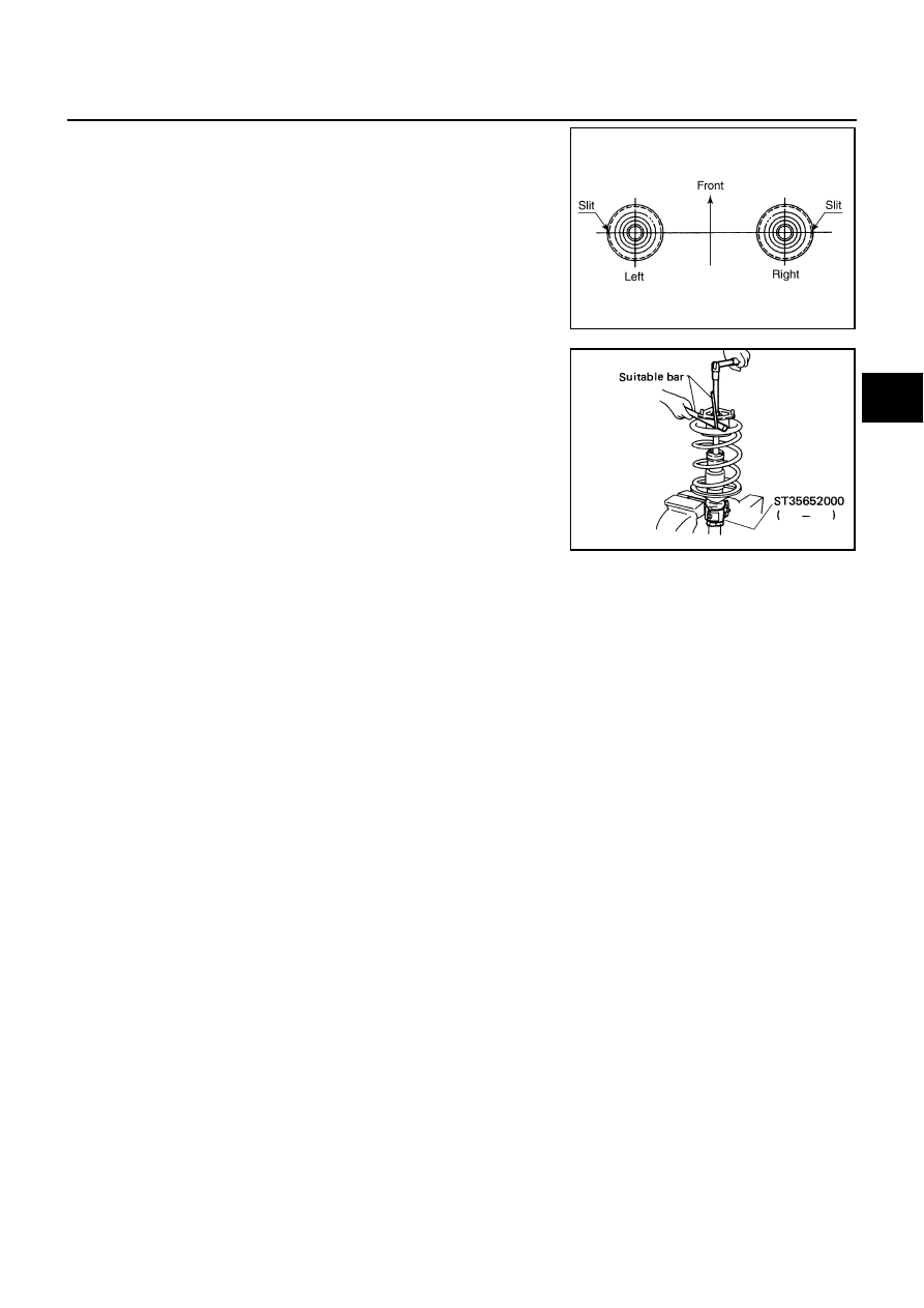
●
Installation position of spring upper seat as shown in the fig-
ure.
5.
Fix strut mounting insulator, then tighten piston rod lock nut with
the specified torque.
CAUTION:
Be careful not to deform strut mounting insulator.
6.
Gradually release spring compressor (commercial service tool), and remove coil spring.
CAUTION:
Loosen while making sure coil spring attachment position does not move.
7.
Remove strut attachment (special service tool) from strut assembly.
8.
Install actuator plate onto strut assembly.
9.
Fix strut mounting insulator, then tighten actuator plate fixing nut with the specified torque.
CAUTION:
Be careful not to deform actuator plate and strut mounting insulator.
SEIA0247E
SFA261B