Infiniti F50. Manual - part 552


  Index      Infiniti     Infiniti F50 - service repair manual 2006 year


Search            


Content   ..  550  551  552  553   ..


Infiniti F50. Manual - part 552


CYLINDER BLOCK

EM-95

C

D

E

F

G

H

I

J

K

L

M

A

EM

Method of Using Plastigauge

Remove oil and dust on the crankshaft pin and the surfaces of
each bearing completely. 

Cut a plastigage slightly shorter than the bearing width, and
place it in crankshaft axial direction, avoiding oil holes.

Install the connecting rod bearings to the connecting rod and the
connecting rod bearing cap, and tighten the connecting rod nut
to the specified torque. 

CAUTION:

Never rotate the crankshaft.

Remove the connecting rod cap and bearings, and using the
scale on the plastigage bag, measure the plastigage width. 

NOTE:
The procedure when the measured value exceeds the repair limit is same as that described in “Method of
Measurement”.

OIL CLEARANCE OF MAIN BEARING
Method of Measurement

Install the main bearings to the cylinder block and main bearing cap. Measure the main bearing inner
diameter with the bearing cap bolt tightened to the specified torque. Refer to 

EM-77, "ASSEMBLY"

 .

(Oil clearance) = (Inner diameter of main bearing) – (Outer diameter of crankshaft journal)

If the measured value exceeds the repair limit, select main bearings referring to the main bearing inner
diameter and crankshaft journal outer diameter, so that the oil clearance satisfies the standard. Refer to

EM-84, "HOW TO SELECT MAIN BEARING"

 .

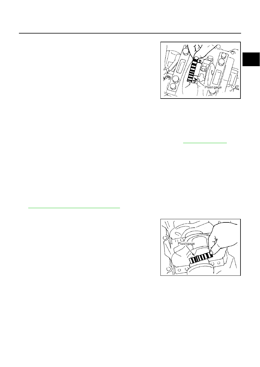
Method of Using Plastigage

Remove oil and dust on the crankshaft journal and the surfaces
of each bearing completely. 

Cut a plastigage slightly shorter than the bearing width, and
place it in crankshaft axial direction, avoiding oil holes

Install the main bearings to the cylinder block and main bearing
cap, and tighten the main bearing bolts to the specified torque. 

CAUTION:

Never rotate the crankshaft.

Remove the bearing cap and bearings, and using the scale on
the plastigage bag, measure the plastigage width. 

NOTE:
The procedure when the measured value exceeds the repair limit is same as that described in “Method of
Measurement”.

SBIA0409E

Standard:

  No. 1 and 5 journals

: 0.001 - 0.011 mm (0.0004 - 0.0004 in)

  No. 2, 3, and 4 journals

: 0.007 - 0.017 mm (0.0003 - 0.0007 in)

Limit:

  No.1 and 5 journals

: 0.021 mm (0.0008 in)

  No. 2, 3, and 4 journals

: 0.027 mm (0.0011 in)

SBIA0410E

EM-96

CYLINDER BLOCK

CRUSH HEIGHT OF MAIN BEARING

When the bearing cap is removed after being tightened to the
specified torque with main bearings installed, the tip end of bear-
ing must protrude.

If the standard is not met, replace main bearings.

Standard

: There must be crush height

SEM502G

SERVICE DATA AND SPECIFICATIONS (SDS)

EM-97

C

D

E

F

G

H

I

J

K

L

M

A

EM

SERVICE DATA AND SPECIFICATIONS (SDS)

PFP:00030

Standard and Limit

EBS003P5

GENERAL SPECIFICATIONS

DRIVE BELTS

INTAKE MANIFOLD AND EXHAUST MANIFOLD

Unit: mm (in)

Cylinder arrangement

V-8

Displacement

cm

3

  (cu in)

4,494 (274.22)

Bore and stroke

mm (in)

93 x 82.7 (3.66 x 3.256)

Valve arrangement

DOHC

Firing order

1-8-7-3-6-5-4-2

Number of piston rings

Compression

2

engine oil

1

Number of main bearings

5

Compression ratio

10.5

Compression pressure                                  

kPa (kg/cm

2

 , psi)/300 rpm

Standard

1,320 (13.5, 191)

Minimum

1,130 (11.5, 164)

Differential limit 
between cylinders

98 (1.0, 14)

Cylinder number

Valve timing

Unit: degree

a

b

c

d

e

f

228

240

0

60

0

48

SEM957C

PBIC0187E

Tension of drive belts

Auto adjustment by auto tensioner

Item

Limit

Surface distortion

Intake manifold upper

0.1 (0.004)

Intake manifold lower

0.1 (0.004)

Exhaust manifold

0.3 (0.012)

EM-98

SERVICE DATA AND SPECIFICATIONS (SDS)

SPARK PLUG (PLATINUM-TIPPED TYPE)

CYLINDER HEAD

Unit: mm (in)

VALVE
Valve Dimensions

Unit: mm (in)

Make

NGK

Type

Standard

PLFR5A-11

Hot

PLFR4A-11

Cold

PLFR6A-11

Plug gap (Nominal)

1.1 mm (0.043 in)

Items

Limit

Head surface distortion

0.1 (0.004)

PBIC0183E

Valve head diameter “D”

Intake

36.0 - 36.3 (1.417 - 1.429)

Exhaust

31.2 - 31.5 (1.228 - 1.240)

Valve length “L”

Intake

 96.57 (3.8020)

Exhaust

94.50 (3.720)

Valve stem diameter “d”

Intake

5.972 - 5.980 (0.2351 - 0.2354)

Exhaust

5.962 - 5.970 (0.2347 - 0.2350)

Valve seat angle “

α

Intake

45

°

15

 - 45

°

45

Exhaust

Valve margin “T”

Intake

0.95 - 1.25 (0.0374 - 0.0492)

Exhaust

1.15 - 1.45 (0.0453 - 0.0571)

SEM188


Content   ..  550  551  552  553   ..